
Universal IR Repeating over Optical Fiber

a technology of optical fiber and optical fiber, applied in the direction of electromagnetic transmission, electrical apparatus, multiplex communication, etc., can solve the problems of unfavorable user space, additional circuitry and wiring, and the inability to control the dtv behind the user, so as to facilitate the user's control of the video source devi

Inactive Publication Date: 2007-12-13
OWLINK TECH
View PDF58 Cites 34 Cited by
  • Summary
  • Abstract
  • Description
  • Claims
  • Application Information

AI Technical Summary

Benefits of technology

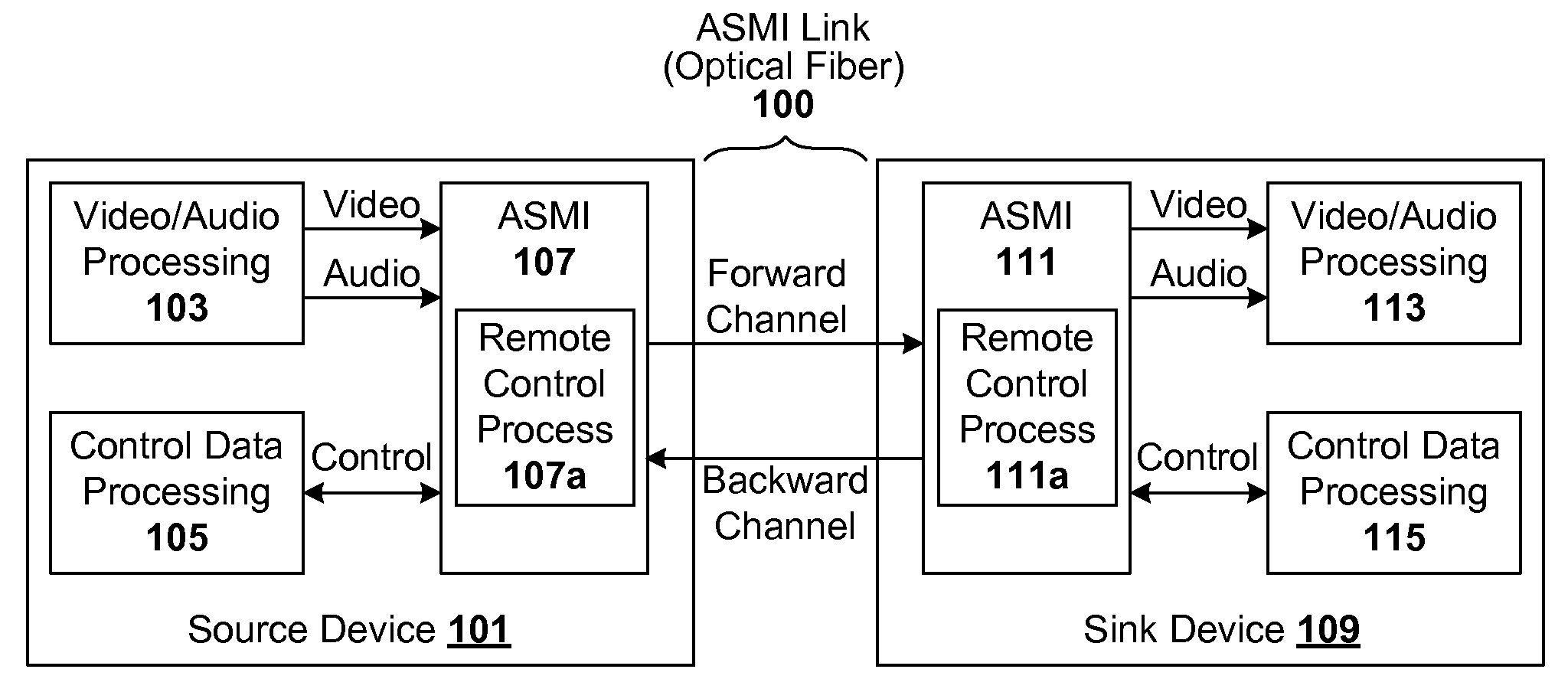
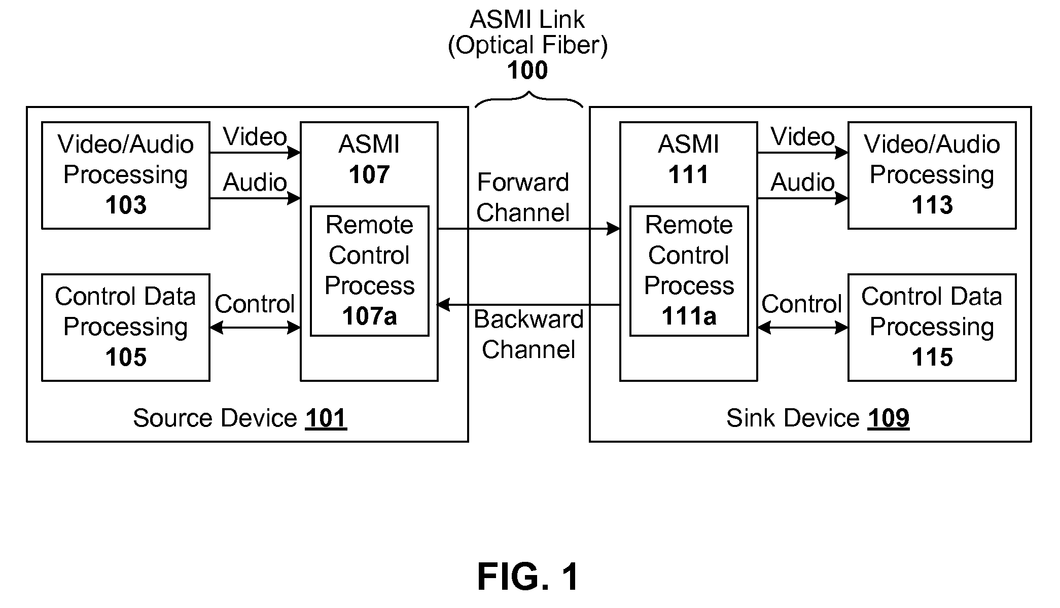
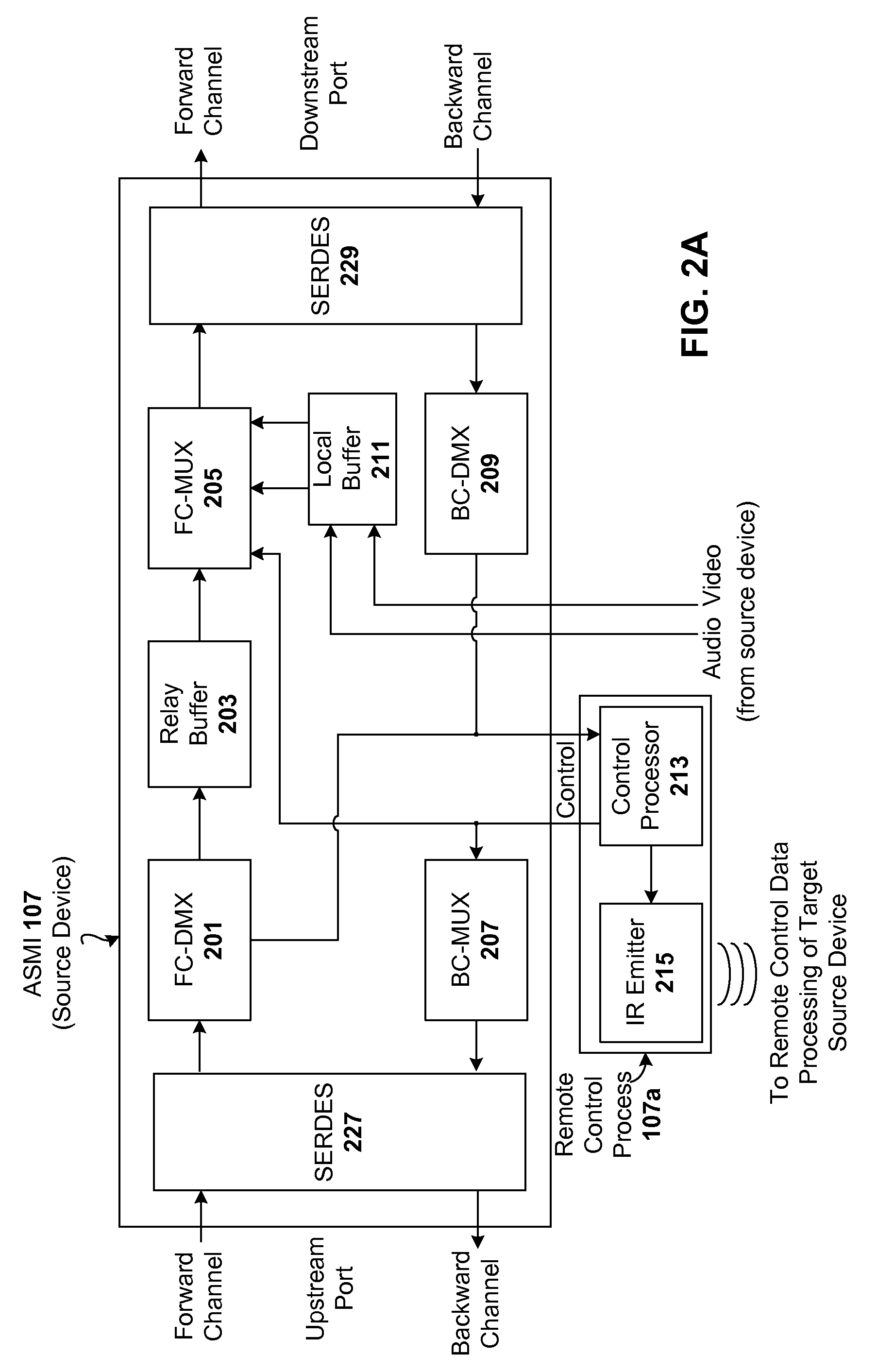
"The present invention provides a method for repeating infrared control signals in a system using a serial communication link, such as an optical fiber, between a source device and a sink device. The method detects infrared remote control data, samples it, and transmits it from the sink device to the source device. The source device then regenerates the infrared control data to control its operation. This allows for secure duplication of IR remote control signals and easy control of the source device without the need for separate cabling. The method is universal as it works with any modulation frequency of the IR signal. The integrated solution makes controlling a video source device easy for a user."

Problems solved by technology

However, remote controls are associated with problems, particularly when there are multiple pieces of equipment to be controlled and at least one piece is not in the user's forward field of view.
This is awkward in that the user has to divide his attention (at least to some extent) to both the DTV in front of him and the DVD player behind him.
Unfortunately, aiming the remote control at the DTV will not control the DVD player behind the user, as the remote control operates on a line-of-sight basis and needs to be pointed at least in the general direction of the device of which it is intended to control.
However, such IR repeater require dedicated circuitry and wiring therebetween, in addition to the components and cabling between the sink and source devices.
Additional circuitry and wiring add to undesirable clutter in the user's space.

Method used


Image

  • Universal IR Repeating over Optical Fiber
  • Universal IR Repeating over Optical Fiber
  • Universal IR Repeating over Optical Fiber

Examples


Embodiment Construction

[0025]A serial transmission protocol and architecture are provided that can be used to forward the raw remote control data in modulated form, between sink (e.g., DTV) and source (e.g., DVD) devices, in addition to other data such as video / audio / control data. The target device need not be in the line of sight of the remote control beam. Daisy-chained devices will pass the remote control signal to the appropriate target device, so that the user can point any remote control at the DTV or other conveniently located device in the system, and still control the actual target device.

[0026]General Overview

[0027]One embodiment of the present invention is a protocol that enables a very high bandwidth (e.g., 1.5 Gbps (gigabits per second) or higher) in one direction for payload data such as video / audio. The transmission path in this direction is called a forward channel. The protocol also enables a relatively low speed communication link in the opposite direction for carrying processing control...


PUM


Abstract

Infrared control signals are repeated and communicated in a system including a source device and a sink device that are communicatively coupled by a serial communication link that includes a forward channel and a backward channel. Modulated infrared remote control data is detected by an infrared detector without de-modulation, and sampled in modulated form. Sampled data corresponding to the modulated remote control signal is transmitted from the sink device to the source device over the serial communication link, which in one example is a single optical fiber. The source device receives the sampled data and regenerates the infrared control data, which is then used to control the operation of the source device.

Description

CROSS-REFERENCE TO RELATED APPLICATIONS[0001]This application is a continuation-in-part application of, and claims priority under 35 U.S.C. § 120 from, U.S. patent application Ser. No. 11 / 423,381 filed on Jun. 9, 2006, entitled “Integrated Remote Control Signaling,” which is incorporated by reference herein in its entirety.[0002]This application is also related to (i) U.S. patent application Ser. No. 11 / 406,558 filed on Apr. 18, 2006, entitled “Protocol for Uncompressed Multimedia Data Transmission,” to (ii) U.S. patent application Ser. No. 11 / 406,875, filed on Apr. 18, 2006, entitled “EDID Pass Through via Serial Channel,” to (iii) U.S. patent application Ser. No. 11 / 173,409, filed on Jun. 30, 2005, entitled “Bidirectional HDCP Transmission Module Using Single Optical Fiber,” to (iv) U.S. patent application Ser. No. 11 / 142,882, filed on May 31, 2005, entitled “High Speed Free Space Optical Detection with Grating Assisted Waveguide,” and to (v) U.S. patent application Ser. No. 10 / 86...

Claims


Application Information

Patent Timeline
Patent Type & Authority Applications(United States)
IPC IPC(8): H04J14/00H04B10/00
CPCH04B10/299H04B10/1143
Inventor GUO, YONGXU, MINGCHENGTZENG, SHING-WU P.
Owner OWLINK TECH
Learn More