Line laying apparatus

a line laying and apparatus technology, applied in the field of line laying apparatus, can solve the problems of high cost and maintenance costs of prior art and the principal disadvantage of complicated mechanisms, and achieve the effect of reducing drag and constant cutting depth

Inactive Publication Date: 2007-12-13
PARENT MICHEL
View PDF20 Cites 27 Cited by
  • Summary
  • Abstract
  • Description
  • Claims
  • Application Information

AI Technical Summary

Benefits of technology

[0014]The guide plate is positioned at said level such as to be visible in use to enable an operative to observe and to maintain a constant depth of cut. The guide plate may be profiled at its leading edge and on its upper and lower surfaces to reduce drag.
[0015]The said at least one passage preferably follows an arcuate path of relatively large curvature in order to provide a smooth run for the line running therewithin.
[0016]Advantageously, the entry and the discharge ends of said passage may be provided with guide tubes of relatively short length to assist in use the guiding of the line into and out of the passage at the entry and discharge ends thereof respectively.

Problems solved by technology

The prior art displays the principal disadvantage of employing complicated mechanisms which are expensive in terms of cost and maintenance.

Method used


Image

  • Line laying apparatus
  • Line laying apparatus
  • Line laying apparatus

Examples


Embodiment Construction

[0025]With reference to the annexed drawings the preferred embodiment of a mole-plough according to the present invention will be herein described for indicative purpose and by no means as of limitation.

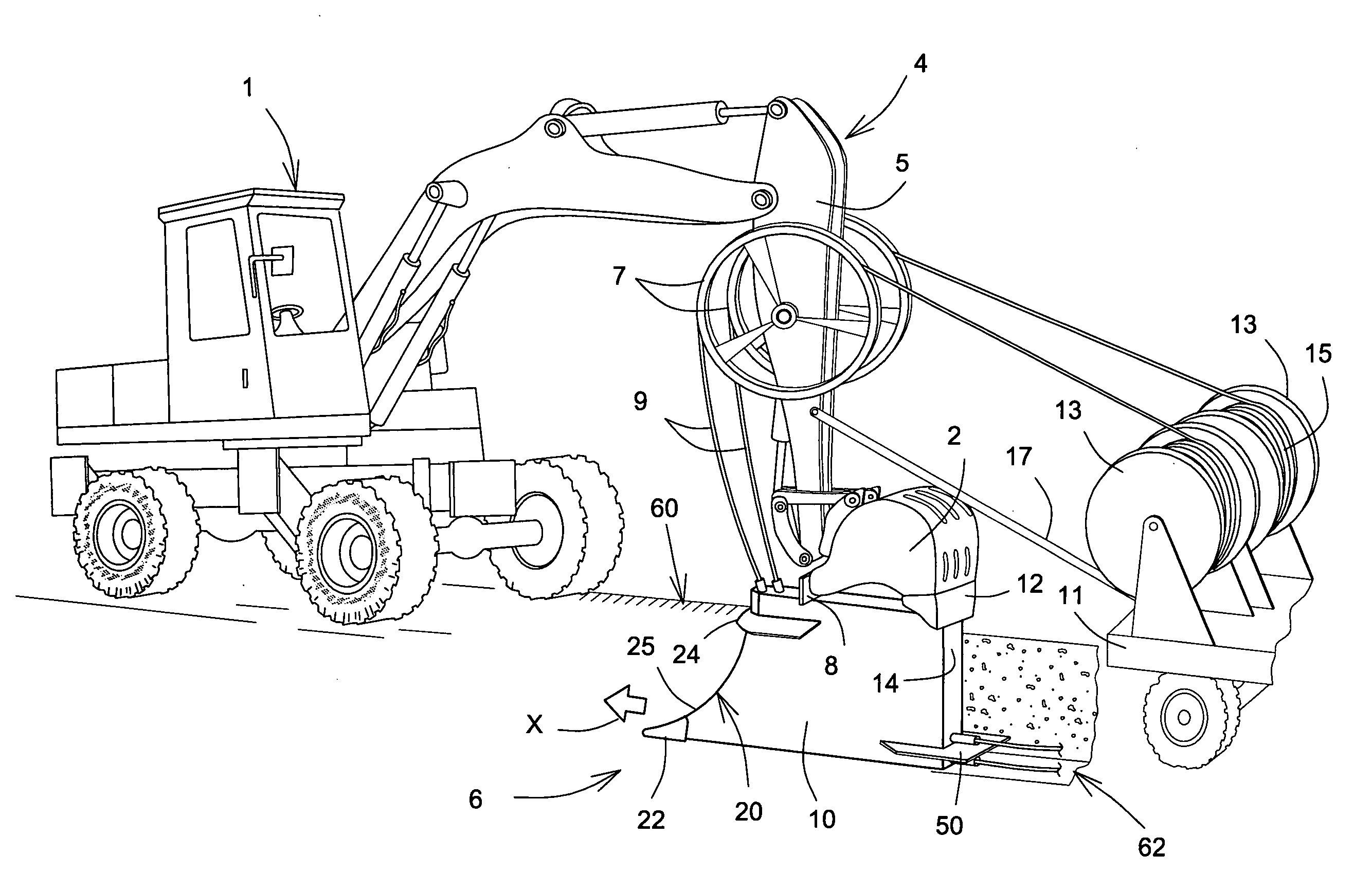
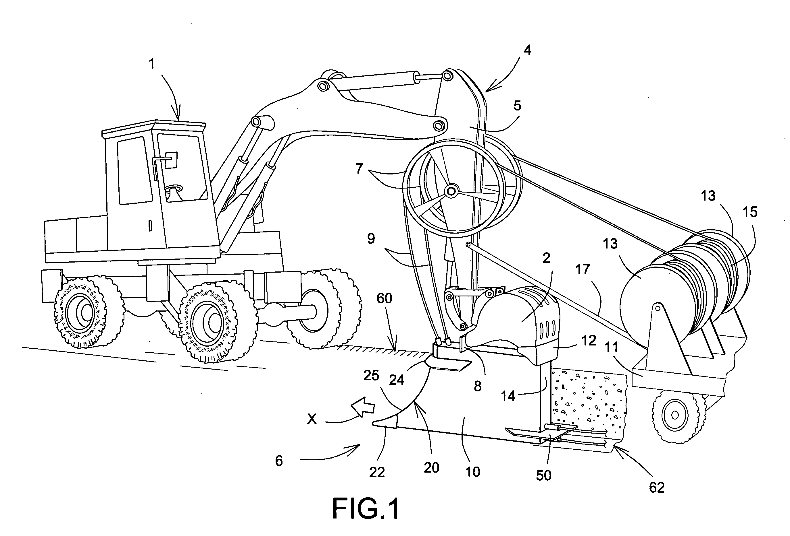
[0026]In FIG. 1 there is illustrated a traction unit in the form of an excavator 1 having an excavator bucket 2 mounted for pivoting movement on an arm arrangement 4 provided on the excavator. The arm arrangement 4 and the pivoting movement of the bucket 2 are hydraulically actuable in conventional manner. One limb 5 of the arm arrangement 4 is provided with guide wheels 7 one for each of two lines 9 shown being fed to a mole-plough 6. A line supply vehicle 11 has feed drums 13 loaded with reeved lines 15 for supplying the mole-plough. A connecting linkage is schematically shown at 17 in FIG. 1 and extends from the vehicle 11 to the arm arrangement 4 whereby in use the vehicle is hauled as a trailer by the excavator.

[0027]The mole-plough 6 is shown in FIG. 1 as being hauled in the di...


PUM


Abstract

A mole-plough for forming a subterranean channel for laying a line includes a body incorporating a leading edge and nose for cutting the channel, a guide plate on the body located at the desired terrain surface level, an arcuate passage within the body for feeding each line to be laid, and a stabilizer disposed adjacent the exit of the passage and extending rearwardly of the body.

Description

FIELD OF THE INVENTION[0001]The present invention relates to apparatus for the laying of lines such as cables, wires, pipes or other elongate relatively flexible lines in a subterranean channel.[0002]More specifically the invention has reference to a mole-plough for forming the subterranean channel and simultaneously feeding the line thereinto.BACKGROUND OF THE INVENTION[0003]The subterranean placement of lines, for example inter alia power lines, water pipes and the like, is well known and practiced and generally involves the cutting of a trench or channel within which the lines are laid in the wake of the cutting stage.[0004]In some existing apparatus such for example as that disclosed in U.S. Pat. No. 3,760,595 to Stewart et al. a digging mole is hauled through the ground to form the subterranean channel and the line is then dragged through the channel to its fullest extent thus leaving the line in a recumbent position in the floor of the channel.[0005]In other prior art proposal...

Claims


Application Information

Patent Timeline
Patent Type & Authority Applications(United States)
IPC IPC(8): F16L1/028
CPCE02F5/101H02G1/06E02F5/102
Inventor PARENT, MICHEL
Owner PARENT MICHEL
Why Eureka
Try Eureka