Lancing of oxygen

a technology of oxygen and lancing, which is applied in the direction of indirect carbon-dioxide mitigation, combustion types, lighting and heating apparatus, etc., can solve the problems of difficult to achieve, low efficiency, and balanced stoichiometric deficit, and achieve the effect of decreasing the amount of nox

Active Publication Date: 2007-12-13
MESSER IND USA INC
View PDF30 Cites 25 Cited by
  • Summary
  • Abstract
  • Description
  • Claims
  • Application Information

AI Technical Summary

Problems solved by technology

It is often desirable to maintain an even temperature distribution within the furnace, which can be difficult to achieve in the case of large furnaces, since the convective heat transfer within the furnace becomes less effective as the volume of the furnace increases.
However, that stoichiometric deficit is balanced against the lanced oxidant at the place where the lanced stream of oxidant intersects the flame.
A problem regarding industrial furnaces with burners using air as the oxidant is that their efficiency is relatively low, and their heat output is relatively high.
Another problem is that the flame of a burner using air as the oxidant produces relatively large amounts of combustion products in the form of NOx compounds, as a result of the elevated flame temperatures.
That is not desirable, since NOx compounds negatively affect the environment, and since there often are limitations present for the volumes of NOx compounds that can be produced in various industrial processes.
However, there is a problem in that there is a substantial cost involved to exchange an air-fed burner with an oxyfuel burner in an industrial furnace.
Furthermore, it is difficult to maintain high temperature uniformity in the entire furnace volume when such a burner is used in large industrial furnaces, because convection decreases as a consequence of the lesser amounts of flue gases that are produced as a result of the lower operation effects for oxyfuel burners.
The result is uneven furnace temperature distribution, with the associated uneven quality of production.
However, that has proven to result in other problems.

Method used


Image

  • Lancing of oxygen
  • Lancing of oxygen

Examples


Embodiment Construction

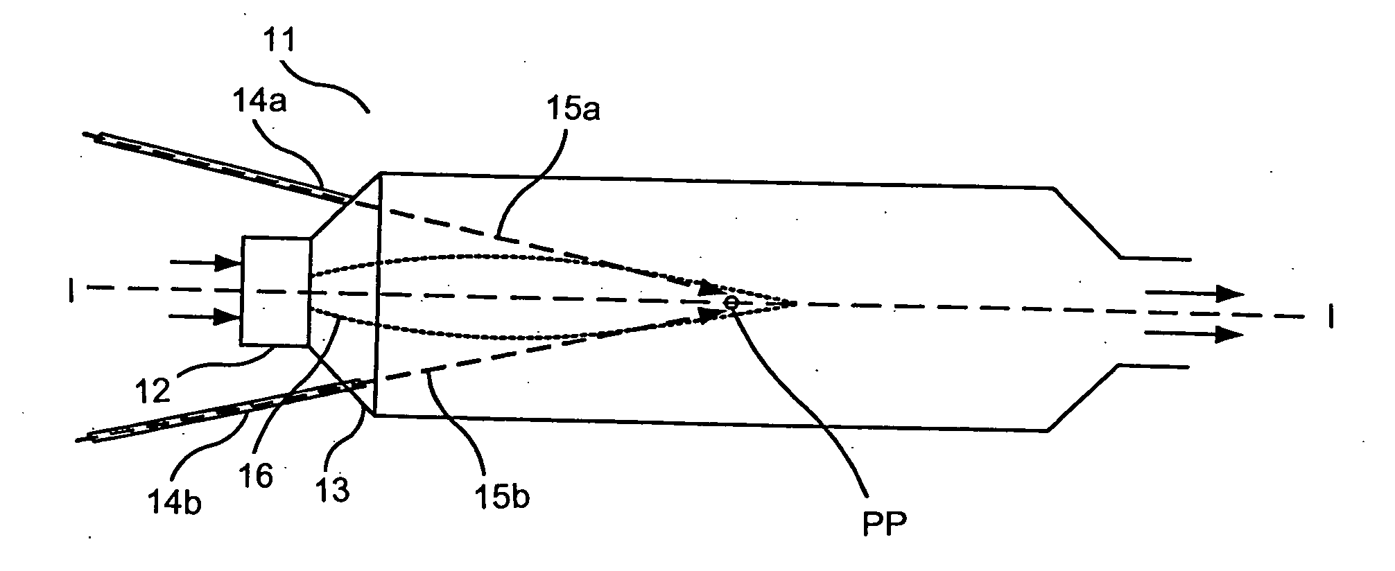
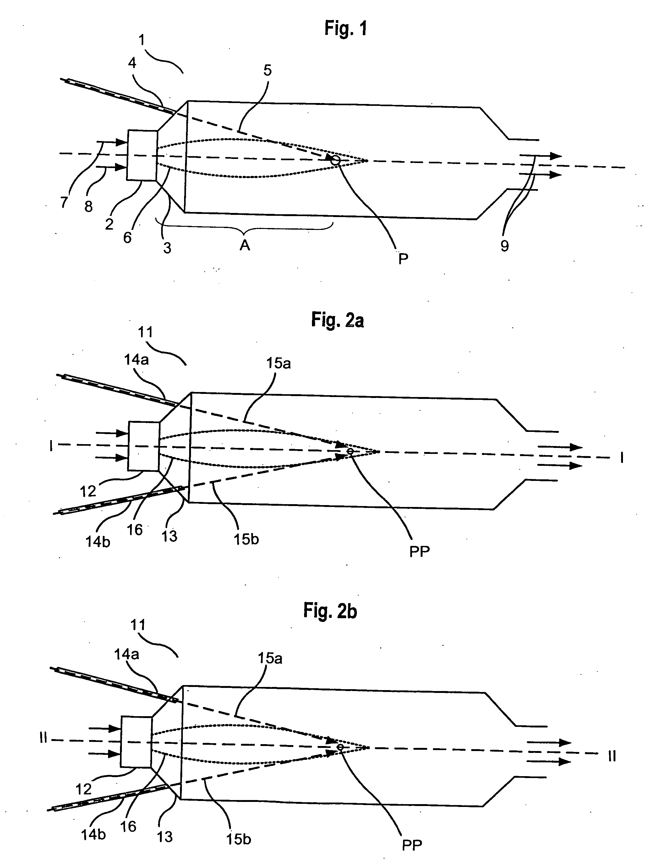
[0020]In FIG. 1, a rotating industrial furnace is depicted. The furnace 1 is heated by the use of a conventional burner 2, using natural gas 7 as the fuel and air 8 as the oxidant. However, it should be understood that the fuel can be any other suitable fuel, such as various liquid or gaseous hydrocarbons. The burner 2 has an associated flame 6, and is mounted in a furnace door 3, which is arranged at a first end of the furnace 1. Through an opening at the other end of the furnace 1 from burner 2, combustion products 9 exit from the furnace.

[0021]The inside diameter of the furnace 1 can, by way of example, be 3.5 m, and it can be about 12 m in length. It can be used for melting out metallic aluminum from so-called dross, which consists of a mixture of aluminum and aluminum oxide. Because of the size of the furnace 1, it must be rotated in order to be able to maintain a sufficiently uniform temperature distribution inside the volume of the furnace. It should be noted, however, that t...


PUM


Abstract

A method for providing uniform heat distribution within a furnace as well as decreasing the amount of NOx in the combustion products, when operating an industrial furnace having at least one conventional burner using air as the oxidant. At least one lance is connected with the furnace, and an oxidant including oxygen gas is flowed into the furnace through the lance to impinge against a flame issuing from the burner at a certain impingement point. The amount of oxygen supplied by the air supply to the burner together with the amount of oxidant issuing from the lance corresponds with the stoichiometric amount for a fuel supplied to the burner. At least 50% of the supplied oxygen for combustion is supplied through the lancing of oxidant, and the oxidant is flowed into the furnace through the lance at a velocity of at least 200 m / s.

Description

BACKGROUND OF THE INVENTION[0001]1. Field of the Invention[0002]The present invention relates to industrial furnaces, and more particularly to a method of uniformly distributing heat within an industrial furnace and of decreasing the quantity of NOx in the combustion products.[0003]2. Description of the Related Art[0004]Today industrial furnaces are widely used for melting and for heat treating metals, for example. Many of those furnaces use one or several burners of the conventional type, which are fed by a fuel such as propane, oil, natural gas, or the like, and fed also with an oxidant. In many cases, air is used as the oxidant.[0005]Such furnaces can be of various sizes. It is often desirable to maintain an even temperature distribution within the furnace, which can be difficult to achieve in the case of large furnaces, since the convective heat transfer within the furnace becomes less effective as the volume of the furnace increases. That problem can be solved, by way of exampl...

Claims


Application Information

Patent Timeline
Patent Type & Authority Applications(United States)
IPC IPC(8): F23M3/04
CPCY02E20/344F23L7/007Y02E20/34F23C7/02
Inventor LODIN, JOHANNES
Owner MESSER IND USA INC
Why Eureka
Try Eureka