

Fluid-filled cervical dilator
- Summary
- Abstract
- Description
- Claims
- Application Information
AI Technical Summary
Benefits of technology
Problems solved by technology
Method used
Image

Examples
Embodiment Construction
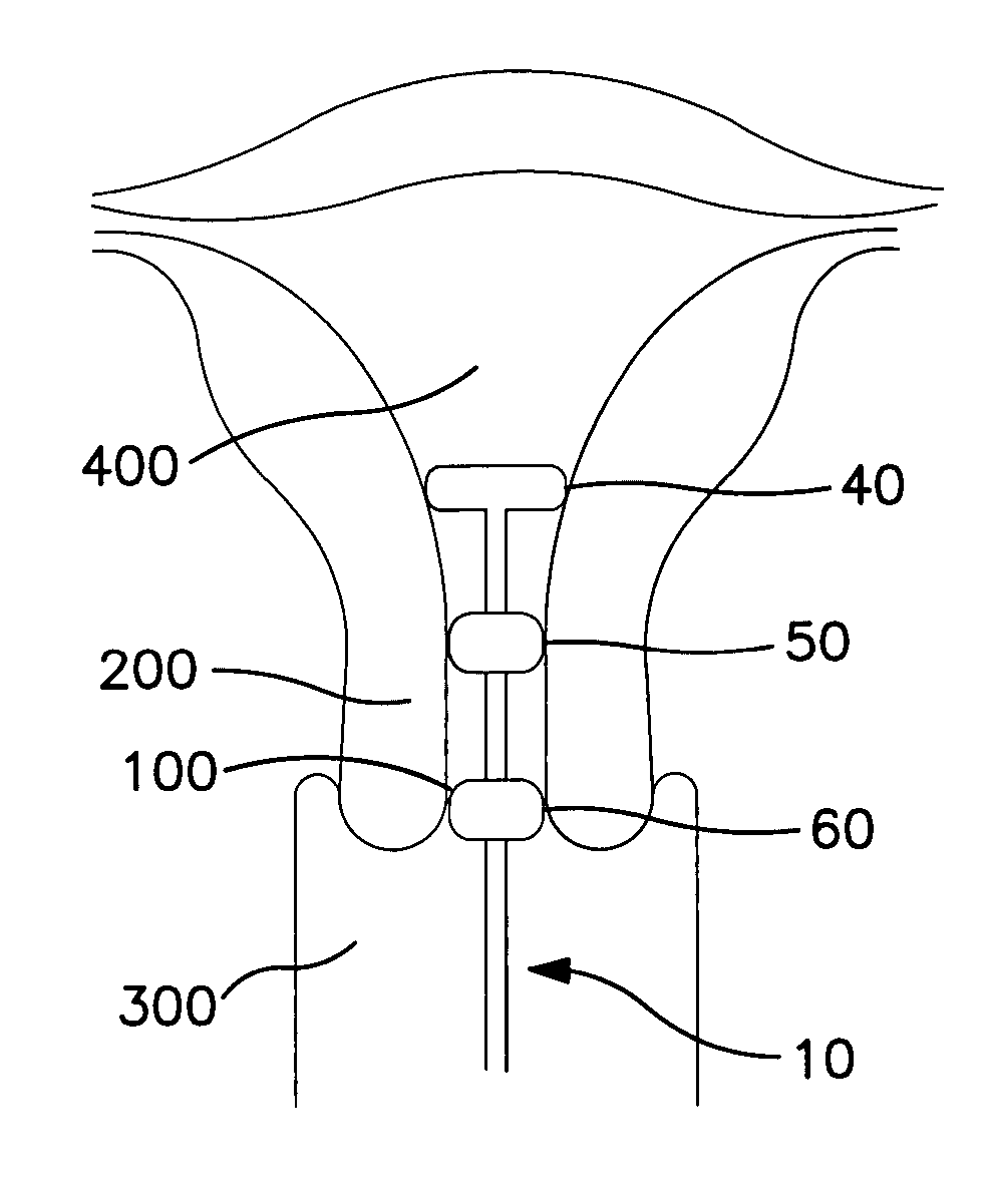
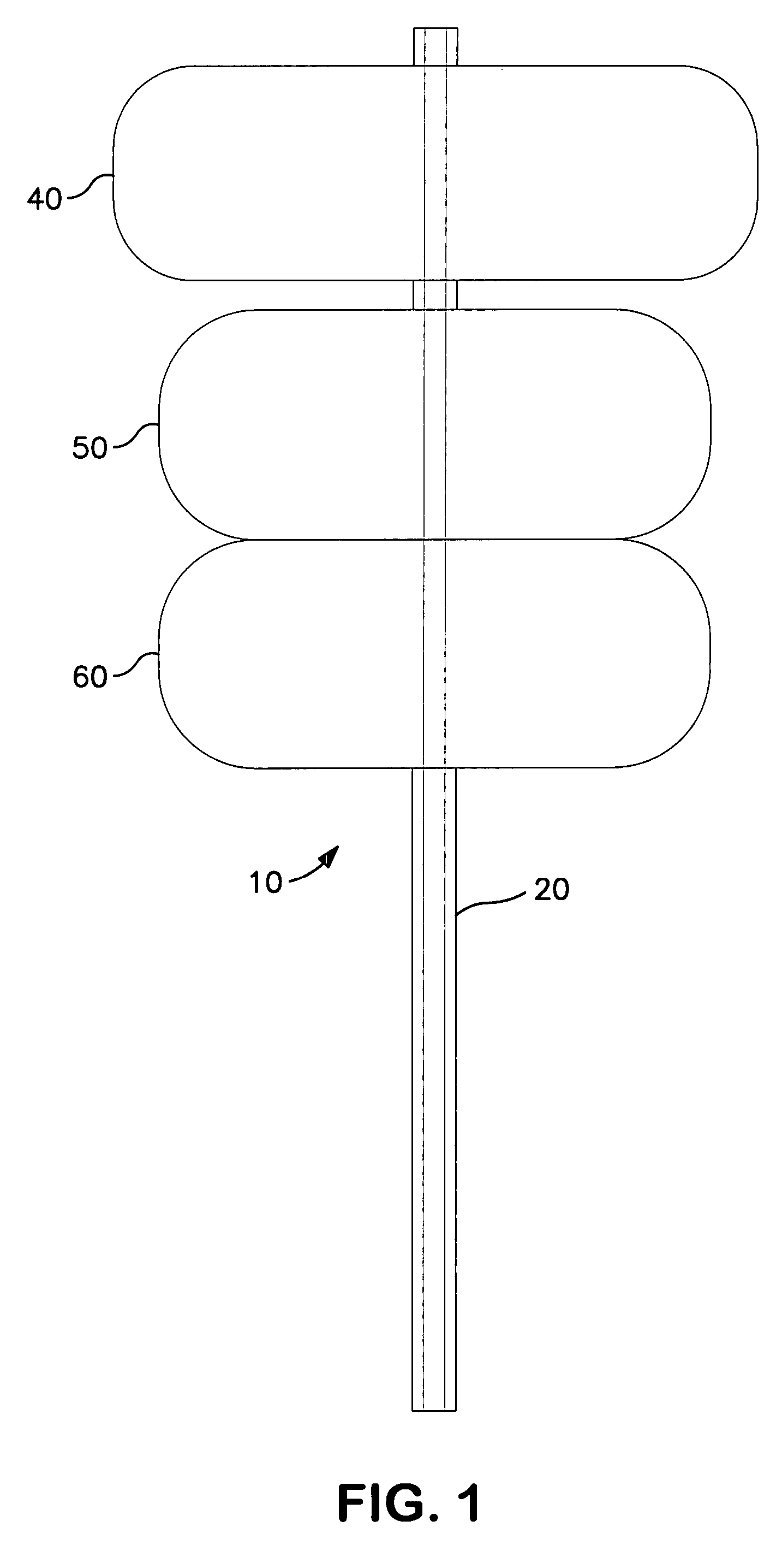
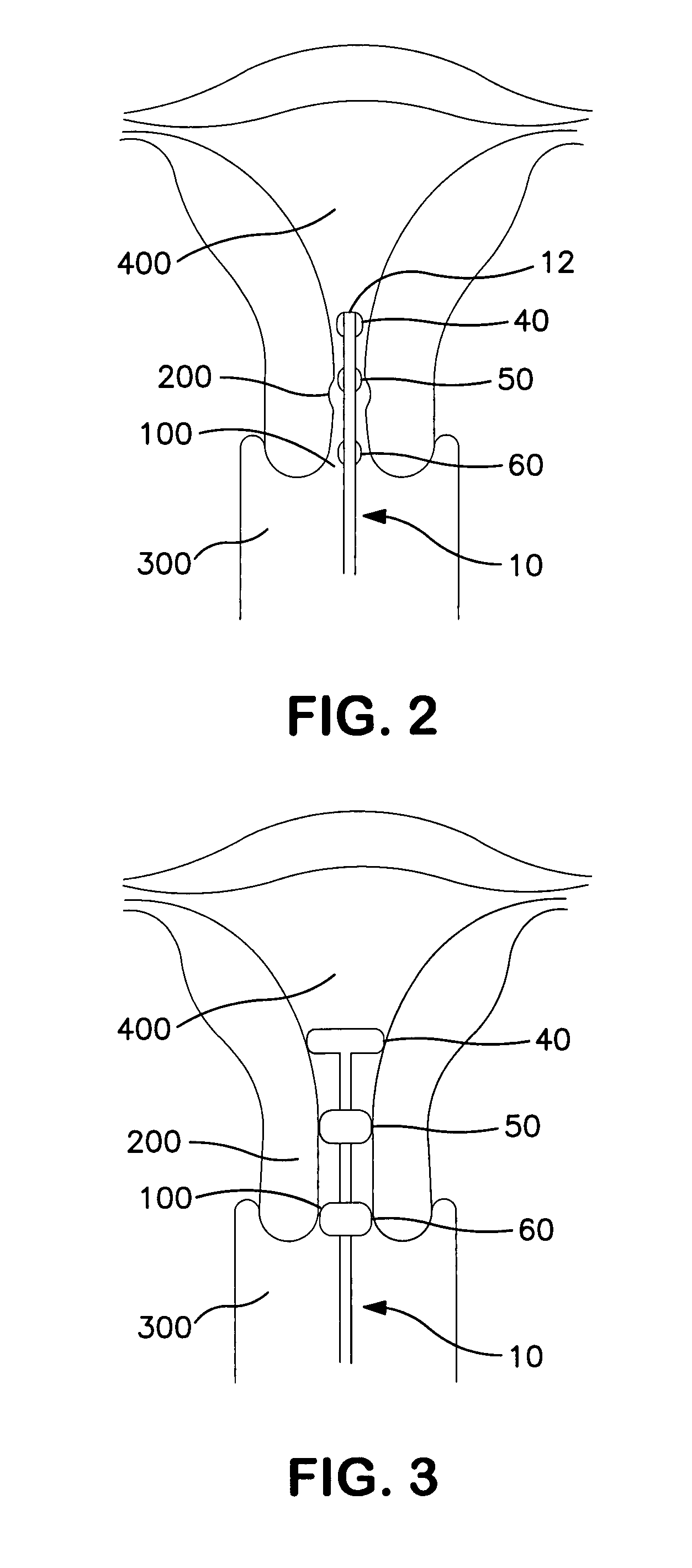
[0011] The device comprises plural, preferably, three elastic balloons as shown in the drawings. The balloons may be constructed of any suitable biocompatible elastic material such as polyurethane, for example. The device is inserted so that the top-most, anchor balloon is above the cervix, and the top balloon is filled with saline from a pump, for example, to inflate and expand the top-most balloon beyond the effective diameter of the upper cervix to anchor the device in the cervical canal. Then, over a period of several hours, the other two balloons, or dilation balloons, are filled with saline from the pump. Two separate catheters or chambers are provided in the interior of the shaft of the device that allow for separate inputs of fluid into the top and remaining balloons, respectively. It will be appreciated by those skilled in the all that any suitable, biocompatible fluid (gas or liquid) may be employed to inflate the balloons.
[0012] The device of the invention is preferably ...
PUM
 Abstract
Description
Claims
Application Information