Vascular thrombectomby apparatus and method of use

Inactive Publication Date: 2007-12-13
CORDIS CORP
View PDF7 Cites 153 Cited by
  • Summary
  • Abstract
  • Description
  • Claims
  • Application Information

AI Technical Summary

Benefits of technology

[0015]A frame, attached to the separation edge, allows the separation edge to maintain flexibility by having a lower modulus of elasticity while preventing the separating edge from buckling as it engages matter and removes it from the wall of the conduit. The frame comprises a plurality of struts that are attached to the separation members. A first group of struts are connected to the separation edge and to a second group of struts that are joined at the distal end of the frame. The second group of struts comprises a plurality of outer struts and a plurality of inner struts attached to and interspersed between the outer struts. The frame is structured so that the stress experienced by the separation edge is evenly distributed across the frame. The frame may take on a variety of spatial configurations such as a truss or a scaffold.
[0016]When the app

Problems solved by technology

Many filters are only partially effective in capturing debris resulting from intervention procedures or naturally occurring debris lodged in the vasculature because deployment of the filter within the conduit may not provide complete filtration.
This may result from failing to maintain an optimum fit of the filter within the vessel or conduit wall resulting in a gap there between.
Where a filter basket is employed another drawback may be encountered if the basket does not fully deploy within the vessel.
Existing filter devices also fail to exhibit the necessary characteristics to capture emboli or thrombi that are attached to a vessel wall or lodged within a vessel.
For example, thrombi are often fixedly attached or lodged within a vessel and significant force is required to dislodge them.
If a filter does not have the proper modulus of elasticity, it will deform and fail to capture or remove the embolic material.
This approach, however, is not well suited for small conduits such as the vasculature located within the human brain, a location where ischemic stroke, blockage of blood vessels by thrombi, originates.
This is a difficult challenge since increased stiffness will

Method used


Image

  • Vascular thrombectomby apparatus and method of use
  • Vascular thrombectomby apparatus and method of use
  • Vascular thrombectomby apparatus and method of use

Examples


Embodiment Construction

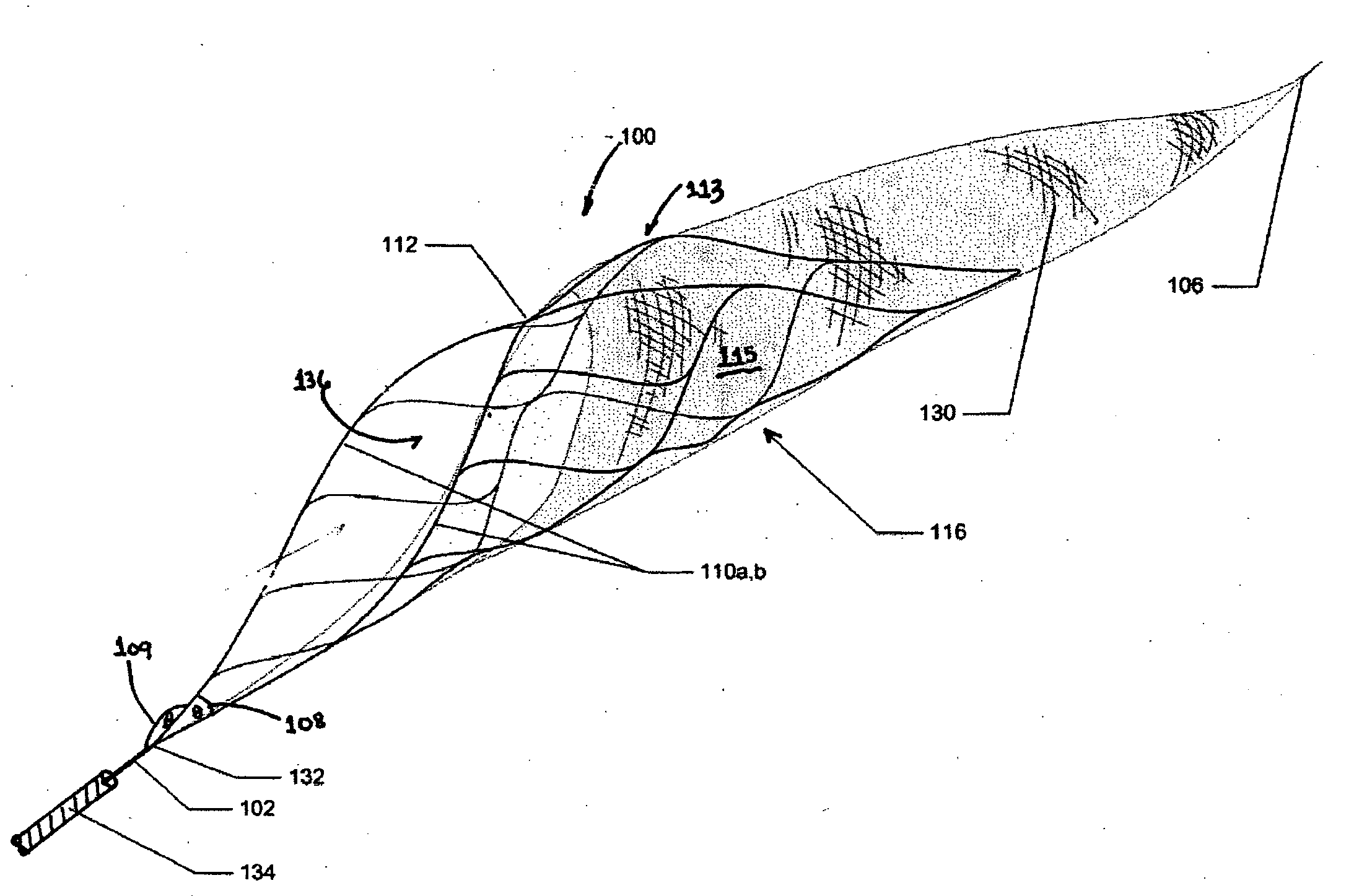
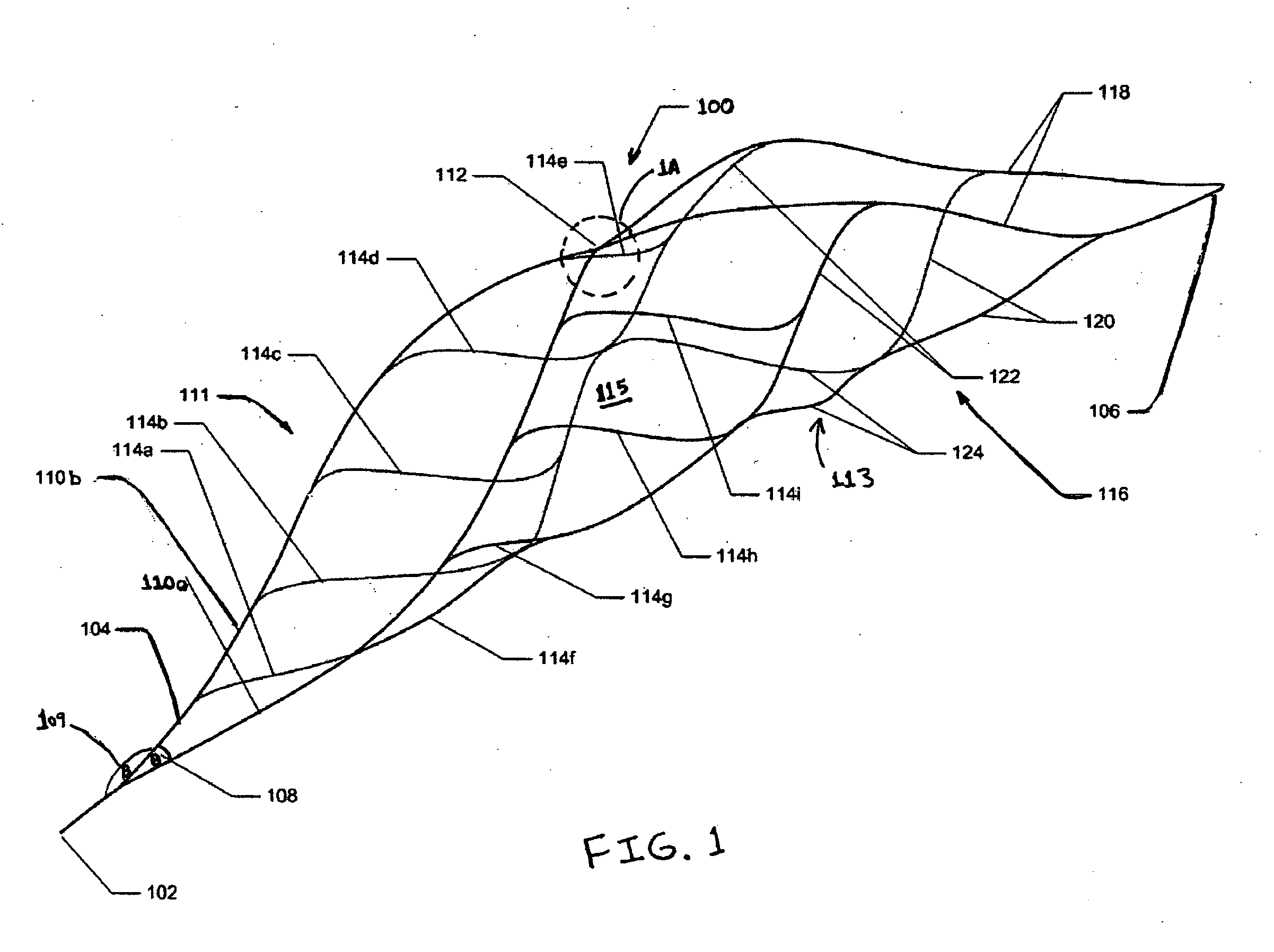
[0027]An apparatus for filtering and removing matter from the interior of a conduit will be described with reference to FIGS. 1-7. As shown in FIG. 1 the apparatus 100 of the present invention generally comprises a separation edge 111 attached to a wire or tether 102, a frame 113 attached to the separation edge 111, and, as shown in FIG. 3, a membrane or net 130 disposed over the frame 113 enclosing its interior 115.

[0028]As shown in FIG. 4, the membrane 130 includes openings along its length that allows fluids found within the conduit to pass through the interior 115 of the frame 113, but prevents matter 144 from escaping. For example, in one embodiment of the invention membrane 130 is a blood permeable sac. If desired, the membrane 130 may be attached to the separation edge 111 to provide structural support thereto augmenting the support provided by the frame 113. The membrane 130 may be constructed from a braided tube of material, wire, or a thin metallic film.

[0029]The metallic ...


PUM


Abstract

An apparatus is provided for removing matter from within a conduit. The apparatus generally comprises a separation edge attached to a wire at its proximal end, a frame attached to the distal end of the separation edge, and a membrane attached to the wire and disposed over the frame enclosing its interior. The membrane generally comprises a net constructed from a vaporized metal deposited on a mandrel. Alternatively, the membrane may comprise a braided tube constructed from wire. The apparatus may be employed as a filter or as a means for actively dislodging matter from the wall of a conduit. When employed as a filter, the apparatus is positioned downstream of the matter where it ensures that matter does not escape downstream as it is being removed. When employed to actively remover matter from a conduit, the apparatus is positioned downstream of the matter. The apparatus is then pulled proximally whereby it engages the matter and dislodges it from the wall of the conduit

Description

FIELD OF THE INVENTION[0001]This invention generally relates to an apparatus and methods used to filter or remove matter from within a body conduit. In particular, this invention relates to a self-expanding device used in interventional procedures such as thrombectomy or embolectomy that resists plastic deformation as it engages, filters and / or removes matter that is entrapped in a conduit of a body.BACKGROUND OF THE INVENTION[0002]Interventional procedures are often necessary to restore the flow of fluids in conduits of the human body. For example, percutaneous interventional procedures may be employed to introduce a stent into the vasculature of a human body to restore the proper flow of blood. During this process matter such as emboli or thrombi may be introduced into the blood stream. In addition, matter may be naturally present in the blood stream or in a conduit of a human body. It is necessary to filter or remove the matter from the conduit to avoid adverse physical affects s...

Claims


Application Information

Patent Timeline
IPC IPC(8): A61M29/00
CPCA61B17/221A61B2017/003A61B2017/00862A61B2017/00867A61F2/01A61F2/013A61F2002/018A61F2230/0008A61F2230/0067A61B2017/2212
Inventor TANAKA, DON A.SOUZA, ALISON M.
Owner CORDIS CORP
Why Eureka
Try Eureka