Wear resistant PVD tool coating containing TiAlN nanolayer films

a technology of tialn nanolayer and tool, which is applied in the direction of manufacturing tools, superimposed coating process, vacuum evaporation coating, etc., can solve the problems of undetected high surface roughness of deposited layers and avoid extremely complex layers, and achieve high young's modulus (modulus of elasticity), improve wear resistance, and high hardness

Active Publication Date: 2022-04-26
WALTER AG
View PDF13 Cites 0 Cited by
  • Summary
  • Abstract
  • Description
  • Claims
  • Application Information

AI Technical Summary

Benefits of technology

[0012]It is an object of the present invention to provide a coated cutting tool with improved wear resistance, a good service life, especially wherein the coating exhibits high hardness, a high Young's modulus (modulus of elasticity) and, at the same time, good adherence of the coating to the substrate.DESCRIPTION OF THE INVENTION

Problems solved by technology

On the other hand, a significant disadvantage of the Arc-PVD is the process-dependent deposition of macroparticles (droplets) caused by the emission of small metal splashes, the avoidance of which is extremely complex.
These droplets lead to an undesirably high surface roughness of the deposited layers.

Method used


Image

  • Wear resistant PVD tool coating containing TiAlN nanolayer films

Examples


example 1

Deposition of Coatings According to the Invention and Comparative Coatings

[0079]In the following examples of the preparation of cutting tools according to the present invention and of comparative examples cemented carbide cutting tool substrate bodies (composition: 12 wt-% Co, 1.6 wt-% (Ta, Nb)C, balance WC; WC grain size: 1.5 μm; geometry: ADMT160608R-F56) were coated in a PVD system as indicated above. The residual stress at the surface of the substrate, measured prior to heating within the deposition chamber, was +200 MPa, i.e., a low tensile residual stress.

[0080]Prior to the deposition, the substrate bodies were pretreated by ultrasonic cleaning in ethanol and plasma cleaning. The PVD reactor was evacuated to 8×10⁻⁵ mbar, and the substrate was pre-treated at 550° C.

[0081]For the deposition of the (Ti,Al)N coatings, two types of targets with different atomic ratios of Ti:Al were used to produce alternately stacked (Ti,Al)N sub-layers being different in respect of the atomic rati...

example 2

Residual Stress, Hardness and Young's Modulus

[0084]For the (Ti,Al)N sub-layer stacks L1 and L2, deposited according to example 1, residual stress, hardness and Young's modulus were measured, as described above. Since the parameters during the deposition of an individual (Ti,Al)N sub-layer stacks L1 or L2, respectively, were held constant, the residual stress within an individual (Ti,Al)N sub-layer stack was constant, but differing from one individual layer stack to another one due to the different compositions and depending on the applied arc current. As described above, each of the (Ti,Al)N sub-layer stacks L1 and L2, respectively, was deposited immediately on the surface of the substrate. The thicknesses of the layer stacks was about 2-4 μm. The results are shown in the following table 2.

[0085]

TABLE 2(Ti,Al)NArc Cur-Pres-Resid-sub-layerrent / sureualVickersYoung'sstackstarget(N2)StressHardnessModulusSample[L1, L2][A][Pa][MPa][HV][GPa]S1L110010+2863234472S2L115010+3483407467S3L120010...

example 3

Surface Roughness

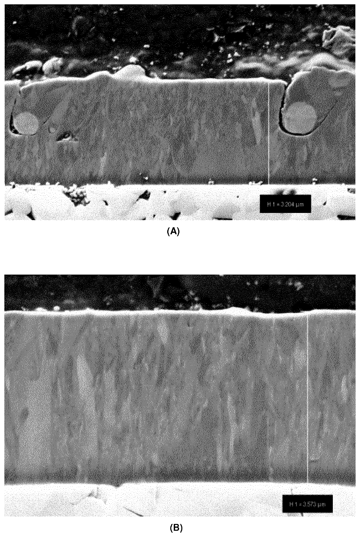
[0089]To compare the influence of the nitrogen pressure in the deposition process, two (Ti,Al)N sub-layer stacks of the type L2 were deposited at 4 Pa and 10 Pa, respectively, and surface roughness measurements were carried out. The results are shown in the following table 2. SEM cross sections of the samples are shown in FIG. 1. It can clearly be seen that the sample deposited at 4 Pa(FIG. 1A), shows larger droplets than the sample deposited at 10 Pa(FIG. 1B). Accordingly, the sample deposited at 10 Pa exhibits a much smoother surface roughness. It has been observed that, generally, smoother surfaces with less droplets and defects are obtained if higher pressure is applied during the deposition process.

[0090]

TABLE 3(Ti,Al)NArcSurfaceSurfacesub-layerCurrent / PressureRoughnessRoughnessstacksTarget(N2)SaSqSample[L1, L2][A][Pa][nm][nm]S7L21504123181S8L21501064125


PUM

PropertyMeasurementUnit
thicknessaaaaaaaaaa
thicknessaaaaaaaaaa
thicknessaaaaaaaaaa

Abstract

A coated cutting tool and a process for the production thereof is provided. The coated cutting tool includes a substrate and a hard material coating, the substrate being selected from cemented carbide, cermet, ceramics, cubic boron nitride, polycrystalline diamond or high-speed steel. The hard material coating includes a (Ti,Al)N layer stack of alternately stacked (Ti,Al)N sub-layers. The layer stack has an overall atomic ratio of Ti:Al within the (Ti,Al)N layer stack within the range from 0.33:0.67 to 0.67:0.33, a total thickness of the (Ti,Al)N layer stack within the range from 1 μm to 20 μm, each of the individual (Ti,Al)N sub-layers within the (Ti,Al)N layer stack of alternately stacked (Ti,Al)N sub-layers having a thickness within the range from 0.5 nm to 50 nm, each of the individual (Ti,Al)N sub-layers within the (Ti,Al)N layer stack of alternately stacked (Ti,Al)N sub-layers being different in respect of the atomic ratio Ti:Al than an immediately adjacent (Ti,Al)N sub-layer, and other characteristics.

Description

RELATED APPLICATION DATA[0001]This application is a § 371 National Stage Application of PCT International Application No. PCT / EP2018 / 073490 filed Aug. 31, 2018 claiming priority to EP 17188809.2 filed Aug. 31, 2017.FIELD OF THE INVENTION[0002]The present invention refers to a metal cutting tool comprising a substrate of cemented carbide, cermet, ceramic, steel or high-speed steel, and a multi-layer wear protection coating applied to the substrate. The invention further relates to a use of the metal cutting tool as well as a process for the production of such a tool.BACKGROUND OF THE INVENTION[0003]Cutting tools, such as those used for example for metal cutting, generally consist of a substrate (base body) made of cemented carbide (hard metal), cermet, steel or high-speed steel having a wear-resistant single-layer or multi-layer coating of metallic hard material layers deposited thereon by means of a CVD process (chemical vapor deposition) or a PVD process (physical vapor deposition)...

Claims


Application Information

Patent Timeline
Patent Type & Authority Patents(United States)
IPC IPC(8): C23C14/06B23C5/00C23C14/32C23C14/35C23C28/04
CPCC23C14/0641B23C5/006C23C14/325C23C14/35C23C28/044C23C28/048C23C14/022C23C30/005
Inventor SCHIER, VEITENGELHART, WOLFGANG
Owner WALTER AG
Why Eureka
Try Eureka