Emergency brain cooling device and method of use

a brain cooling and brain technology, applied in the field of emergency brain cooling devices and methods of use, can solve the problems of reducing the chance of tissue damage, and irreversible damage to brain tissue, and achieve the effect of cooling the brain and/or body core temperature of the patien

Inactive Publication Date: 2007-12-13
GAYMAR IND
View PDF4 Cites 4 Cited by
  • Summary
  • Abstract
  • Description
  • Claims
  • Application Information

AI Technical Summary

Benefits of technology

[0012]The present invention is directed to a scarf having a sealable pocket. Within the pocket is a Joule-Thompson gas chamber having an activation device. When the activation device is triggered, the compressed gas is released from the Joule-Thompson gas chamber through at least one restriction aperture into the sealable pocket. That release results in at least the walls of the sealed pocket being cooled. Prior to being cooled or after being cooled, the scarf is placed over a portion of the patient's body. Preferably, the scarf is positioned over at least one of the patient's carotid arteries, preferably both, to effectively cool the patient's brain and / or body core temperature.

Problems solved by technology

It is well known in the medical art that depriving the brain of oxygen for even a short period of time results in irreversible damage to the brain tissue.
However, it is also known that lowering the temperature of the brain (hypothermia) slows its metabolic activity, and reduces the chance of tissue damage when the oxygen supply is diminished.
However, out in the field, when medical emergencies occur, brain cooling must quickly and expeditiously take place without access to the sophisticated equipment available in the hospital operating room.
Lasersohn's device is not practical for emergency situations.
Bags of ice, however, are difficult to maintain on a patient.
Using adhesives can be deleterious as well.
Some adhesives could cause adverse allergic reactions and / or cause further damage to the patient's skin.
Bags of ice have further problems in that ice is a commodity that is difficult to transport and maintain for extensive periods of time in an emergency like setting, like an ambulance.
This collar system is not adaptable for immediate emergency responses.
This device is bulky is difficult to place over and under a patient.

Method used


Image

  • Emergency brain cooling device and method of use
  • Emergency brain cooling device and method of use
  • Emergency brain cooling device and method of use

Examples


Embodiment Construction

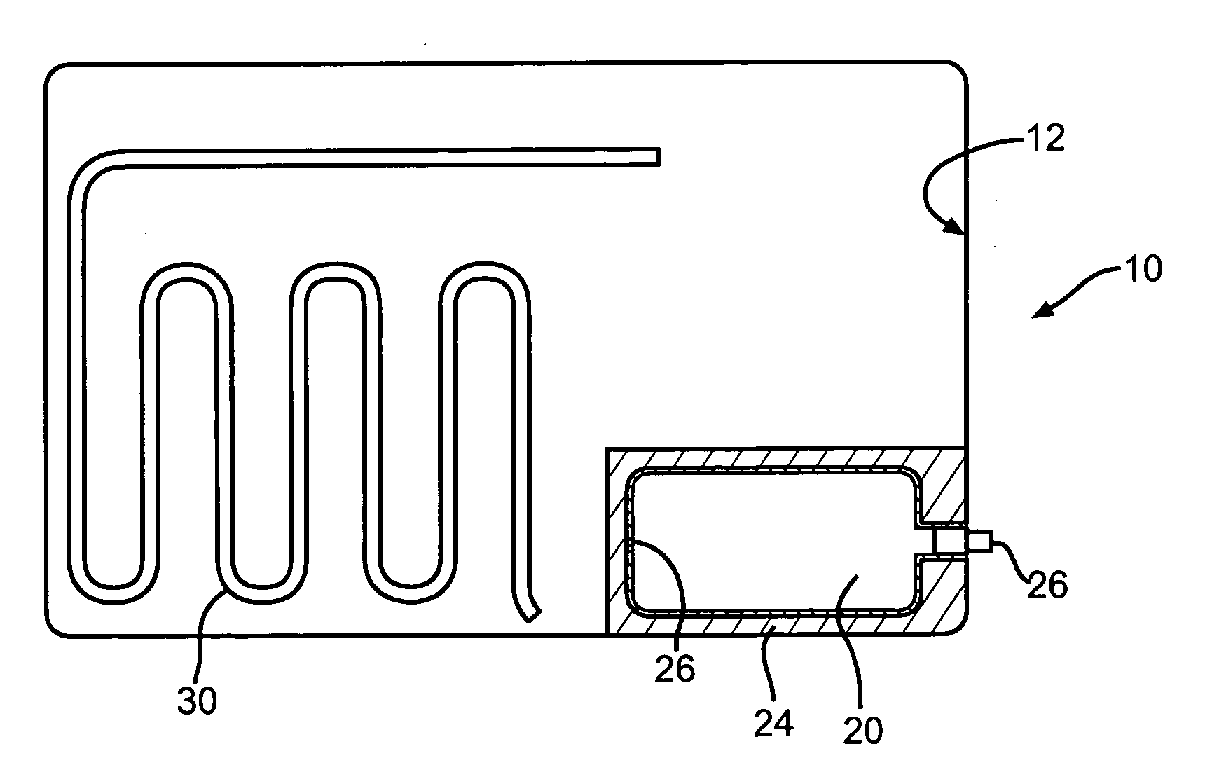
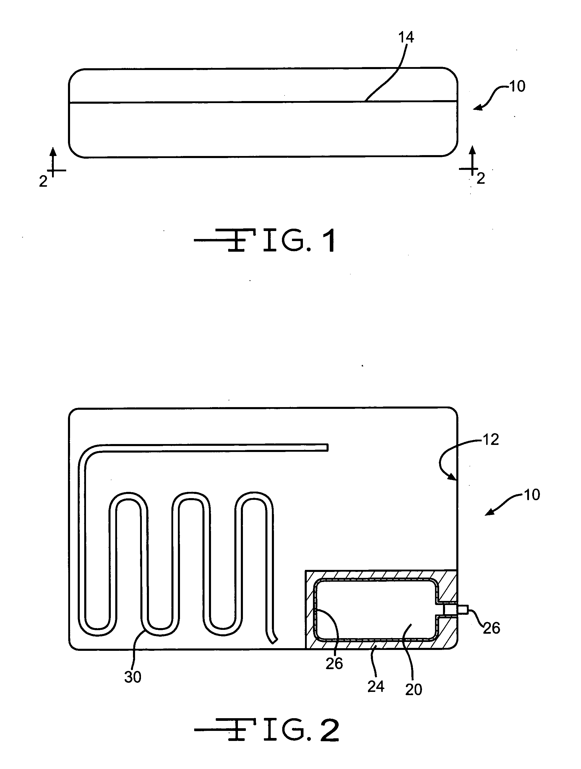
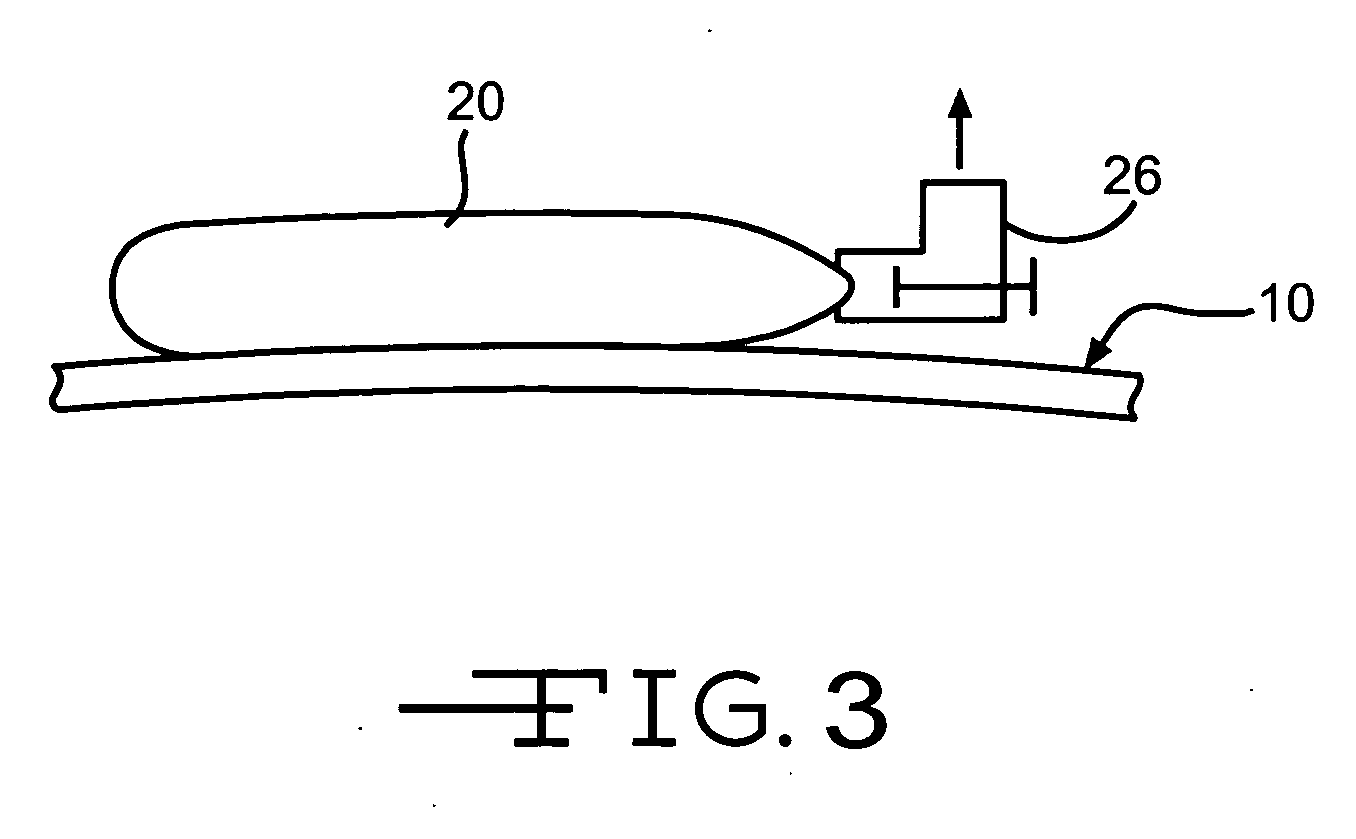
[0016]FIG. 1 depicts an embodiment of the cooling mechanism 10. The cooling mechanism looks like a scarf. The scarf 10 can be applied to any part of a patient's body, but is usually applied to the neck of the person desiring either cooling after or during exercise. The scarf 10 is preferably formed from any material that allows the efficient transfer of thermal energy to a patient without losing its attribute of being a cooling mechanism that can easily wrap around a patient's body part, preferably the neck. Examples of the material for the cooling mechanism include and are not limited to cotton toweling material, conductive polymer material, natural fibers, polymeric material, polymeric material with rivet like devices interspaced therein, and flexible metallic material. For some of these materials, there may be an insulation layer (not shown) within the interior chamber 12 to ensure that the desired cold thermal temperature of the cooling mechanism 10 is maintained.

[0017]Within th...


PUM


Abstract

The present invention is directed to a scarf having a sealable pocket. Within the pocket is a Joule-Thompson gas chamber having an activation device. When the activation device is triggered, the compressed gas is released from the Joule-Thompson gas chamber through at least one restriction aperture into the sealable pocket. That release results in at least the walls of the sealed pocket being cooled. Prior to being cooled or after being cooled, the scarf is placed over a portion of the patient's body. Preferably, the scarf is positioned over at least one of the patient's carotid arteries, preferably both, to effectively cool the patient's brain and/or body core temperature.

Description

FIELD OF THE INVENTION[0001]The present invention is directed to a device designed to decrease the temperature of a brain.BACKGROUND OF THE INVENTION[0002]It is well known in the medical art that depriving the brain of oxygen for even a short period of time results in irreversible damage to the brain tissue. Such deprivation occurs during stroke, respiratory arrest, cardiac arrest, trauma and other severe bodily disturbances that slow or otherwise hinder the flow of oxygenated blood to the brain. However, it is also known that lowering the temperature of the brain (hypothermia) slows its metabolic activity, and reduces the chance of tissue damage when the oxygen supply is diminished.[0003]At present, operative neurosurgery and cardiac surgery is done in many cases using hypothermia for the specific purposes of maintaining cerebral and cardiac function. In an operating room, this requires use of a cooling module in conjunction with heart / lung bypass techniques by which the patient's ...

Claims


Application Information

Patent Timeline
Patent Type & Authority Applications(United States)
IPC IPC(8): A61F7/00
CPCA61F7/02A61F2007/0058A61F2007/0009
Inventor CAZZINI, KARL
Owner GAYMAR IND
Why Eureka
Try Eureka