Skew clock tree

a clock tree and skew technology, applied in the direction of instruments, specific program execution arrangements, program control, etc., can solve the problems of large pipelined digital circuits, provoking random failures in digital circuits, and reducing the performance or malfunction of digital circuits

Inactive Publication Date: 2007-12-13
AZURO UK
View PDF26 Cites 13 Cited by
  • Summary
  • Abstract
  • Description
  • Claims
  • Application Information

AI Technical Summary

Benefits of technology

[0016]The displayed skew clock tree may include a first displayed clock tree including the first clock root and each clock sink associated with the first clock root and a second displayed clock tree including the second clock root and each clock sink associated with the second clock root. The computer system

Problems solved by technology

Additionally, a large, pipelined digital circuit may easily contain hundreds of clocked elements.
Clock skew occurs when a clock signal arrives at different cells or components (e.g., two flip-flop clock inputs) on the digital circuit at different times. Clock skew can result from differences in interconnect capacitance due to differing segment lengths, the placement of clock buffers, and the number, placement, and types of clocked elements being driven by the clock.
Poor clock distribution can therefore cause reduced performance or malfunction i

Method used


Image

  • Skew clock tree
  • Skew clock tree
  • Skew clock tree

Examples


Embodiment Construction

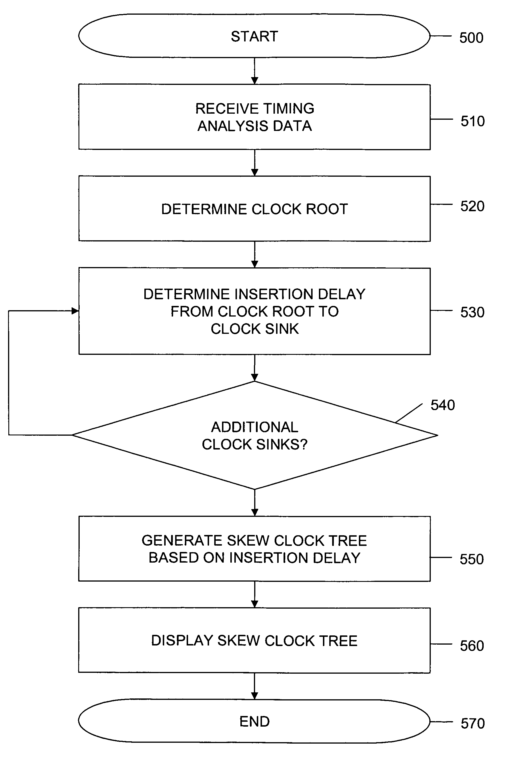
[0033]According to the present invention, techniques are provided which assist in the design process of digital circuits through the visualization of skew clock trees. In some embodiments, a user (e.g., a circuit designer) of a computer system selects timing analysis data (from sources such as a placed gate netlist, DEF / PDEF, SDC, lib, or LEF file) for a digital circuit. The computer system acts upon the timing analysis data to determine one or more clock roots of the digital circuit. The computer system identifies the various components connected between the one or more clock roots and one or more clock sinks associated with each of the one or more clock roots. The computer system then determines an insertion delay or propagation time delay between the one or more clock roots and the one or more clock sinks associated with each of the one or more clock roots of the digital circuit. The computer system then generates corresponding graphical representations of skew clock trees of the...


PUM


Abstract

A method, graphical user interface, and computer program product on a computer readable medium are disclosed for presenting a user with a display of a skew clock tree for a digital circuit design. In the preferred embodiment, a computer system receives timing analysis data for a digital circuit. The computer system determines a propagation time delay between a first clock root and each of a plurality of clock sinks of the digital circuit associated with the first clock root based on the timing analysis data. The computer system then displays the first clock root and each clock sink associated with the first clock root of the skew clock tree along an axis representing time delay. In the displayed skew clock tree, each clock sink is positioned along the axis relative to the first clock root based on each clock sink's determined propagation time delay.

Description

BACKGROUND OF THE INVENTION[0001]The present invention relates to electronic design automation, and more particularly to visualization of skew clock trees of digital circuits.[0002]High-performance synchronous integrated circuits have traditionally been characterized by the clock frequency at which the integrate circuits operate. Additionally, a large, pipelined digital circuit may easily contain hundreds of clocked elements. Circuit designers typically ensure proper timing of digital circuits by carefully planning and implementing distribution of clocks and clock signals throughout the digital circuits. At numerous steps in the design process, a circuit designer gauges the ability of the circuit to operate at specified speeds by measuring clock delay in the digital circuit.[0003]One technique to assist in the planning and implementation of a digital circuit is to develop a clock tree for the digital circuit. The clock tree describes the interconnect geometry that connects a clock t...

Claims


Application Information

Patent Timeline
IPC IPC(8): G06F17/50
CPCG06F2217/62G06F17/5031G06F30/3312G06F30/396G06F2117/04
Inventor EAKINS, PAULCUNNINGHAM, PAULWILCOX, STEPHEN
Owner AZURO UK
Why Eureka
Try Eureka