Ultrasonic Flaw Detection Method For Roller Bearing, And Method For Detecting Flaws

a flaw detection and ultrasonic technology, applied in the direction of instruments, mechanical equipment, specific gravity measurement, etc., can solve the problems of fine cracks occasionally opening in the raceway, high contact pressure and repeated rolling fatigue on the roller bearing, and achieve the effect of superior accuracy

Inactive Publication Date: 2007-12-20
NSK LTD
View PDF0 Cites 30 Cited by
  • Summary
  • Abstract
  • Description
  • Claims
  • Application Information

AI Technical Summary

Benefits of technology

[0081] The present invention enables provision of an ultrasonic flaw detection method effective for providing rolling bearing products which do not involve a concern about occurrence of a short-life product.
[0082] Under the flaw detection method according to the eleventh aspect of the present invention, an area where reflected echoes of predetermined intensity or more are continually measured over a predetermined distance in a

Problems solved by technology

Since a rolling bearing rotates while undergoing the load exerted on a shaft by way of rolling elements, the rolling bearing is subjected to high contact pressure and repeated rolling fatigue between rolling elements and inner and outer rings.
Moreover, in relation to a rolling bearing, fine cracks occasionally open in a raceway during turning operation in the course of manufacture of the rolling bearing or under the excessive conditions employed during grinding operation.
When the fine cracks still remain at the time of completion of the rolling bea

Method used


Image

  • Ultrasonic Flaw Detection Method For Roller Bearing, And Method For Detecting Flaws
  • Ultrasonic Flaw Detection Method For Roller Bearing, And Method For Detecting Flaws
  • Ultrasonic Flaw Detection Method For Roller Bearing, And Method For Detecting Flaws

Examples


first embodiment

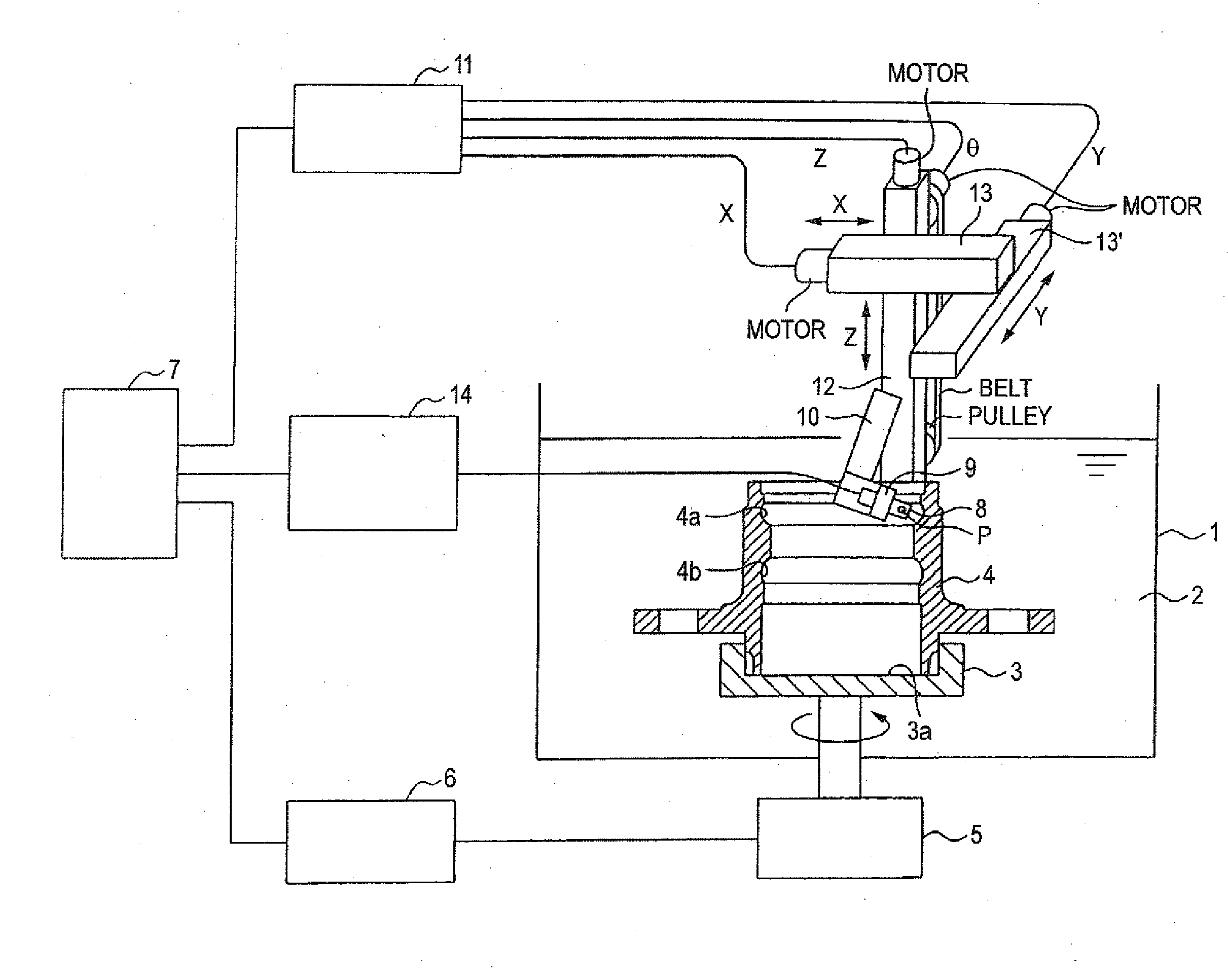
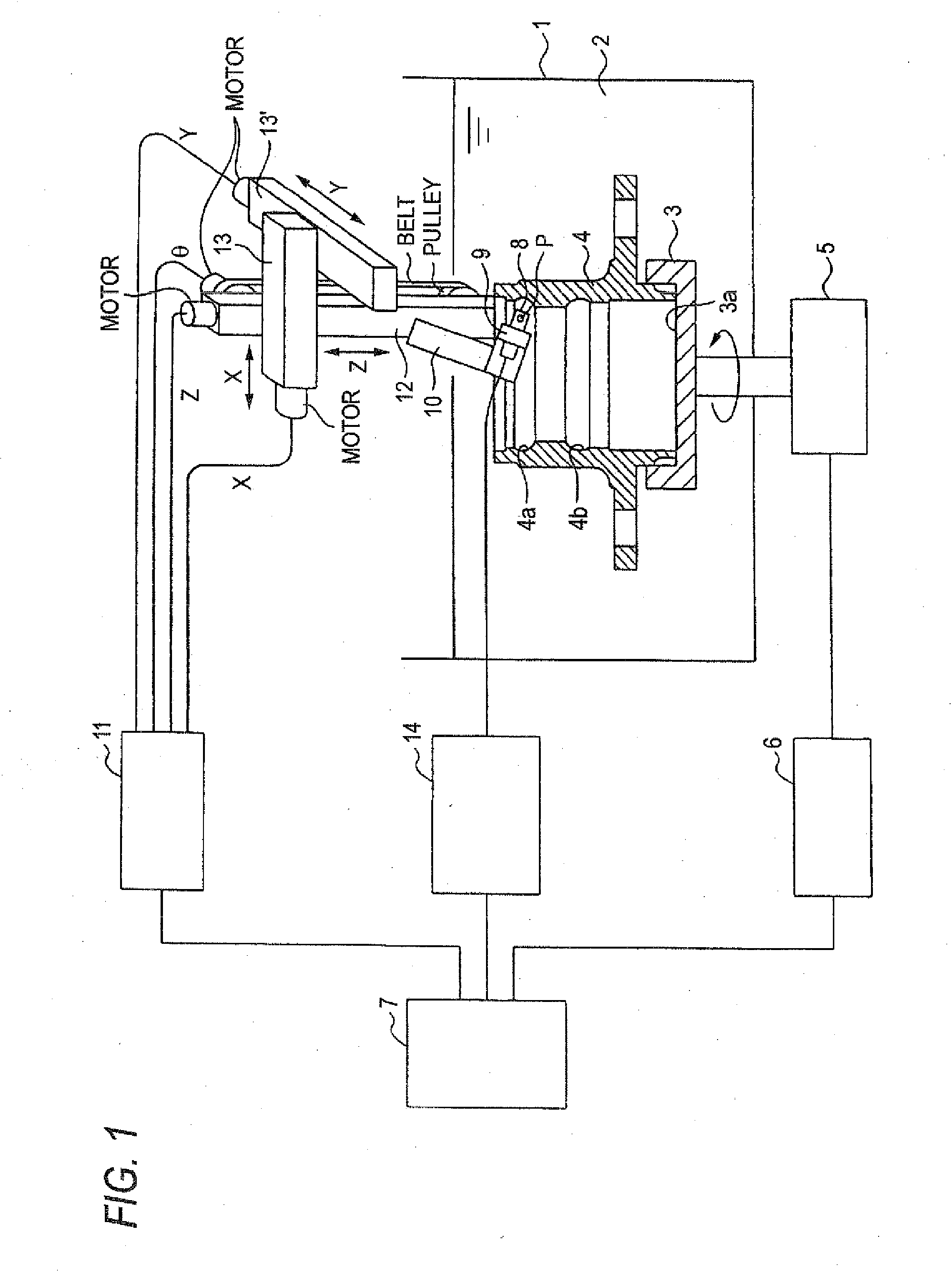
[0148] The present invention will first be described by reference to the configuration of an ultrasonic flaw detector of the present embodiment.

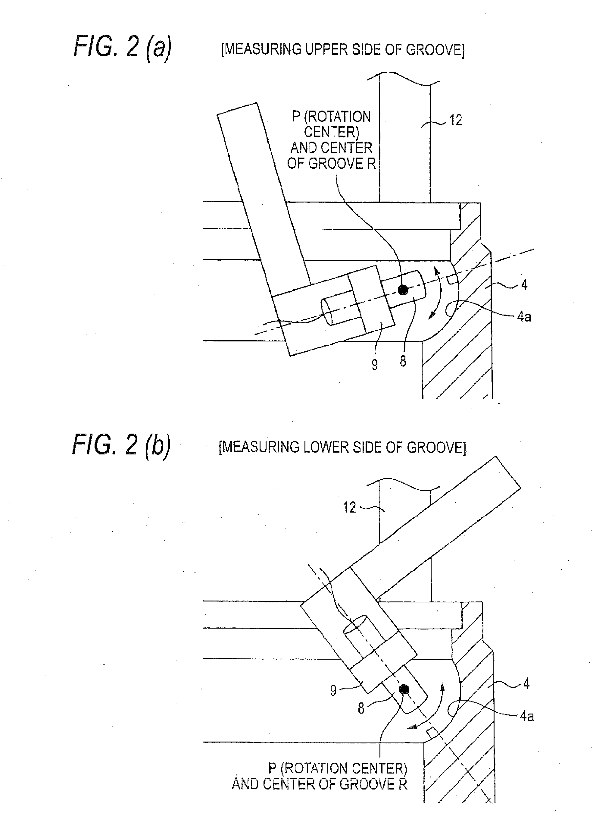
[0149]FIG. 1 is a general block diagram of an ultrasonic flaw detector according to an embodiment of the present invention, and FIGS. 2 and 3 are fragmentary enlarged views.

[0150] In FIG. 1, reference numeral 1 designates a bath where is stored kerosene or another liquid hydrocarbon 2 serving as an ultrasonic wave transmission medium. In the present embodiment, kerosene is used as the liquid hydrocarbon 2, and a rust inhibitor is added to the kerosene. An outer ring 4 of a bearing and a jig 3 are positioned at lower locations within the bath 1. A fitting section 3a which enables fitting of the outer ring 4 of the bearing with its axis being oriented vertically is provided in an upper portion of the jig 3, and the jig 3 is rotationally driven by a motor 5 around an axis of rotation concentric to the axis of the bearing. The motor 5 is contr...

second embodiment

[0190] A second embodiment will now be described by reference to the drawings. Elements analogous to those of the first embodiment will be described while being assigned the same reference numerals.

[0191] From the viewpoint of productivity, flaw detection is initiated as early as possible. Meanwhile, when time has elapsed very quickly since a workpiece was immersed, an effect for removal of air bubbles or dust becomes deficient, and pseudo noise attributable to air bubbles or the like frequently arises. Thus, there arise a request for productivity and a request for prevention of noise. An inspection method for minimizing noise through a round of operations for effecting an inspection by immersing a workpiece in a medium and immediately transporting the workpiece after conduction of a pass / fail test is desired as the ultrasonic inspection method for fulfilling the requests.

[0192] The present inventors have performed considerable studies about shortening of an inspection time and en...

first example

[0198] The present example is directed toward performance of ultrasonic flaw inspection by use of: an ultrasonic flaw detector, such as that mentioned above, by means of incorporating an inspection process for ultrasonically detecting flaws subsequent to a finishing process in a bearing production process, and liquid hydrocarbon as a medium.

[0199]FIG. 4 shows example procedures of the process when ultrasonic flaw detection of the present embodiment is performed.

[0200] For comparison, Table 1 shows results of comparison among a conventional example 1 wherein ultrasonic flaw detection was performed after a round bar (a forging) process (see arrow A), a conventional example 2 wherein ultrasonic flaw detection was performed after heat treatment (see arrow B), a conventional example 3 where ultrasonic flaw detection is performed after grinding (see arrow C) while a water-based material is taken as a medium, and the first example of the present invention.

TABLE 1UltrasonicInspectionPro...


PUM


Abstract

An ultrasonic flaw detection method for detecting a flaw which inspects a raceway surface 4a of an outer ring 4 as a surface to be inspected. After the surface to be inspected has finished undergoing finish grinding, a flaw is ultrasonically detected while liquid hydrocarbon 2 including kerosene is taken as an ultrasonic wave transmission medium.

Description

TECHNICAL FIELD [0001] The present invention relates to a ultrasonic flaw detection method for inspecting flaws in a raceway surface or a rolling contact surface of a rolling bearing, and more particularly to a ultrasonic flaw detection method for a rolling bearing effective for detecting a short-life product and providing highly-reliable rolling bearings guaranteed to have stable life. BACKGROUND TECHNIQUE [0002] Since a rolling bearing rotates while undergoing the load exerted on a shaft by way of rolling elements, the rolling bearing is subjected to high contact pressure and repeated rolling fatigue between rolling elements and inner and outer rings. Consequently, when a flaw is present in the raceway surface or a position located immediately below the surface, the flaw poses great influence on rolling-fatigue life. For this reason, in relation to a material used for a rolling bearing, no flaws are expected to be present in the surface or inside of a raceway surface of an end pro...

Claims


Application Information

Patent Timeline
IPC IPC(8): G01N29/04
CPCF16C33/64G01N2291/2696G01N29/28G01N2291/2636G01N2291/0289G01N29/041G01N2291/0234G01N2291/0423G01N2291/044G01M13/045
Inventor KIUCHI, AKIHIRO
Owner NSK LTD
Why Eureka
Try Eureka