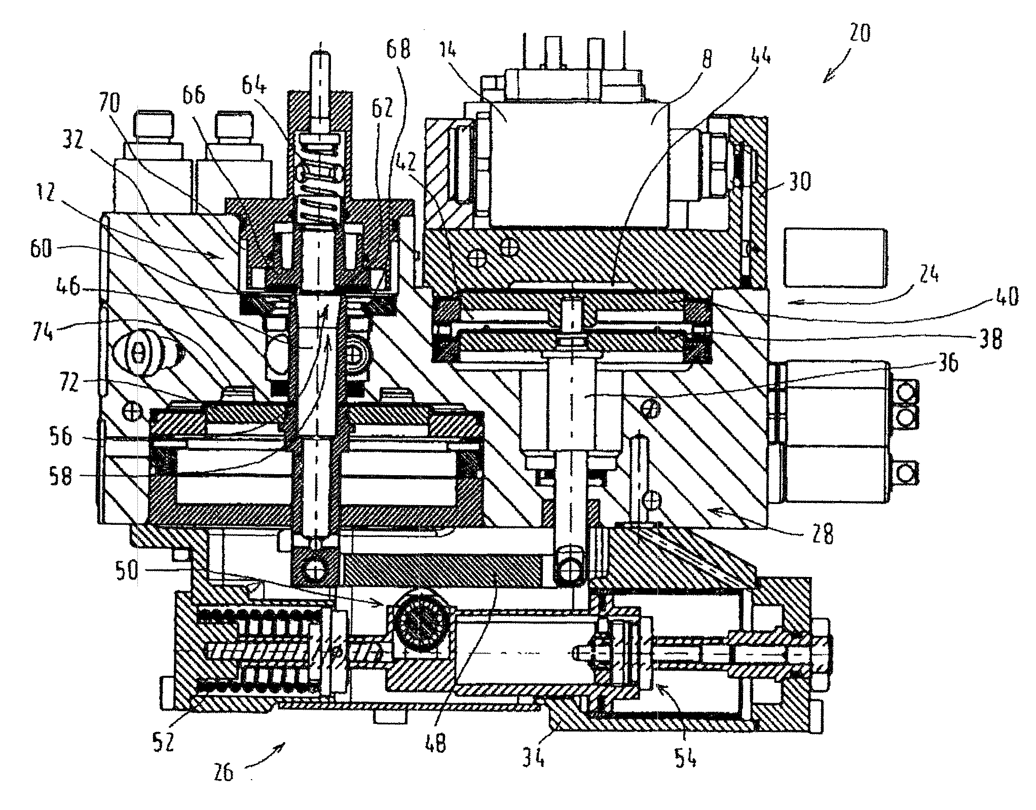
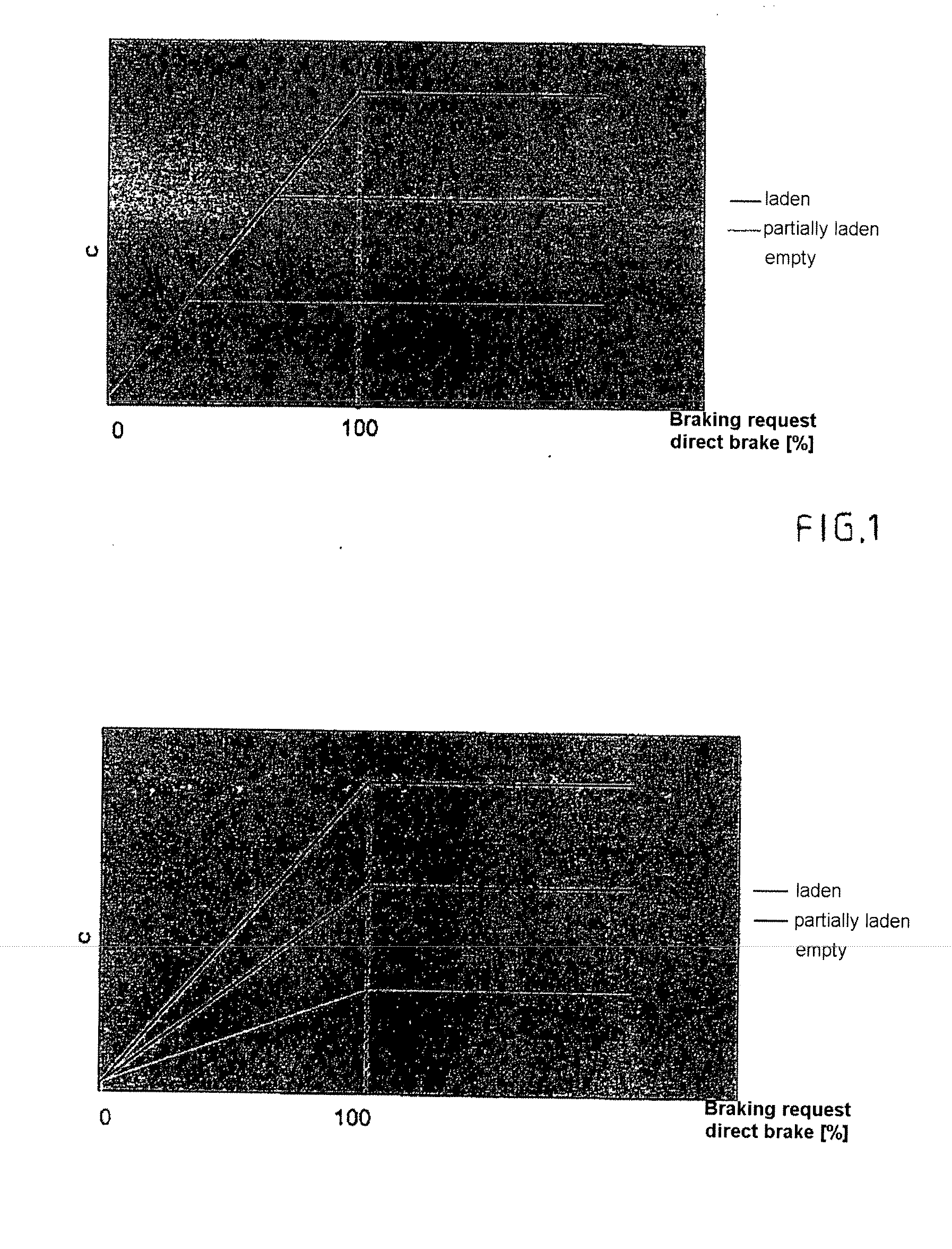
[0011] The advantages which can be achieved with this arrangement comprise, in particular, the fact that, on the one hand, load correction is performed continuously on the direct brake device and the regulating range extends over the entire braking request from 0% to 100%, as is apparent in particular from the diagram according to FIG. 2 which shows the profile of the
brake pressure C generated by the direct brake device, plotted against the braking request for three load states: empty, partially laden and fully laden. Accordingly, the full range of the braking request can be regulated completely from 0% to 100% in all load states, as a result of which short braking distances can be achieved in all load states. Pressure limitation does not take place until the braking request of 100% is reached.
[0012] The measures specified in the subclaims permit advantageous developments and improvements of the invention specified in patent claim 1.
[0013] The
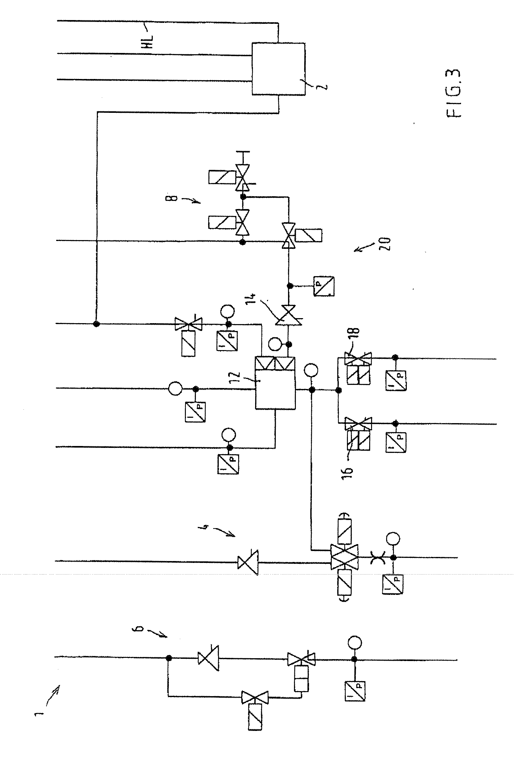
pressure regulator and the pressure limiting valve, the
relay valve, the selection device, the transmission and the
actuator device are each particularly preferably accommodated in separate housings which are placed together in a block. This results in a particularly compact design, and in addition the individual functional blocks of the pressure
regulator and pressure limiting valve,
relay valve, selection device, transmission and the actuating device can be premounted in their respective housing.
[0014] According to a further measure, the selection device is formed by a
piston diaphragm arrangement, having a first
piston diaphragm which is connected in an axially fixed fashion to a first
piston rod, and a second piston diaphragm which transmits force only in one direction to the first
piston rod, a first pressure chamber which is subjected to the pilot control pressure of the indirect brake being formed between the first piston diaphragm and the second piston diaphragm, and a pressure chamber which is subjected to the maximum pilot control pressure of the direct brake being formed between the second piston diaphragm and a wall of the housing. This arrangement ensures significantly higher reliability compared to the
shuttle valve from the prior art in which undefined switched positions cannot be ruled out.
[0015] The transmission is preferably formed by a lever linkage, with the first
piston rod, a second
piston rod which activates the
relay valve and with a toggle lever, the first piston rod being coupled to one end of the toggle lever, and the second piston rod being coupled to its other end, and it being possible to set the position of a support, arranged between the
coupling points, of the toggle lever as a function of the respective load state of the rail vehicle by means of the actuating device. In particular, the support of the toggle lever can be adjusted by means of a piston of the actuating device, said piston being loaded by a loading pressure.
[0017] A particularly simple design is obtained if a valve closing body of the outlet valve is formed at the end of the second piston rod which faces away from the toggle lever and said piston rod is connected in an axially fixed fashion to a piston or a piston diaphragm which is loaded by the brake pressure in a direction which opens the outlet valve.
[0018] The function of the brake system will become clear through the following description of an exemplary embodiment of the invention.

