Methods and apparatus relating to improved visual recognition and safety

a visual recognition and safety technology, applied in the direction of shade, point-like light source, light support device, etc., can solve the problems of incident scene not providing a suitable or safe position, the problem is obvious the most difficult, and the emergency worker is often required to work in dangerous conditions. , to achieve the effect of high-concentration outpu

Inactive Publication Date: 2007-12-20
TRAYNOR NEIL
View PDF5 Cites 134 Cited by
  • Summary
  • Abstract
  • Description
  • Claims
  • Application Information

AI Technical Summary

Benefits of technology

[0041] Maybe pressed, cut, folded, treated, laminated or any combination to improve flexibility.
[0166]106. Built in blackboard (or target board) to improve visual identification of a signal
[0169]109. The bottom of the illuminated badge projects extra light to improve identification.

Problems solved by technology

Emergency workers are often required to work in dangerous conditions where there is no available general light (including sunlight) or extremely low levels of illumination.
However, the problem is obviously most difficult where there is a low level of visibility such as in smoke, silt, rain and other opaque atmospheres or when non-lineal angles of viewing or a line of sight for an observer does not exist or is obscured.
Some incident scenes may not provide a suitable or safe position for the mounting of emergency lights.
Another problem is the glare factor created by a bright intensive light within a dark background.
Often they will wear a miner's type headlight to allow their hands to be free, unfortunately, this means they are often invisible to people behind them.
Fellow workers may find it impossible to identify a ‘Buddy’ team mate because of the high source of glare generated by the other's headlamp or torch in the low levels of light often encountered.
This loss of ‘Night Vision’ may result in placing one's self in additional danger.
A further complication is that it is often difficult for safety workers and others to identify their ‘Chain of Command’ leaders in poor ambient light or Vis versa.
Essential tooling or plant may be invisible or difficult to find on a disaster site in the masking atmospheres caused by smoke, chemical haze or other indistinct reasons.
Additional obstacles also exist when trying to supervise the security of a site in low light.
Normal safety lanterns and large torches are cumbersome and unsuitable for many applications.
Unfortunately, they may not be capable of getting their vehicle close to the scene of a disaster, or alternatively providing an essential early warning for other people.
Flares and other forward warning signs are not always possible to use, because of high winds, fire risk, chemical or water hazards.
Most existing domestic smoke detectors only provide an audio warning or a small internal light that has a limited area of illumination.
The preferred mounting location for a smoke detector may not position the light in the most suitable position to provide suitable evacuation illumination.
Current road studs all project above the current road surface thus being subject to extreme impact damage from traffic.
This impact causes wear that may move the stud from its original site or a reduction in its reflective properties.
Thus they conserve the remaining energy in batteries weaken with prolonged use.

Method used


Image

  • Methods and apparatus relating to improved visual recognition and safety
  • Methods and apparatus relating to improved visual recognition and safety
  • Methods and apparatus relating to improved visual recognition and safety

Examples


Embodiment Construction

[0038] The invention will now be discussed in detail by reference to the following Figures and Legend:

LEGEND

Summary of Numbers Used to Illustrate Drawings

Number Description

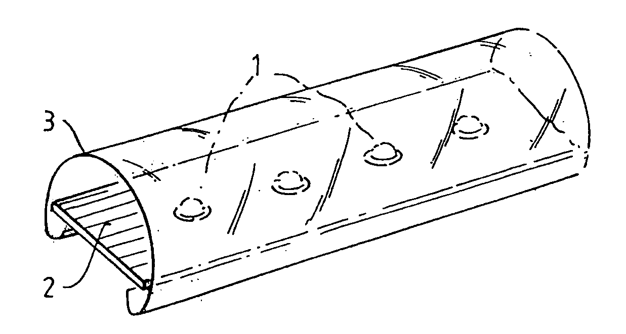
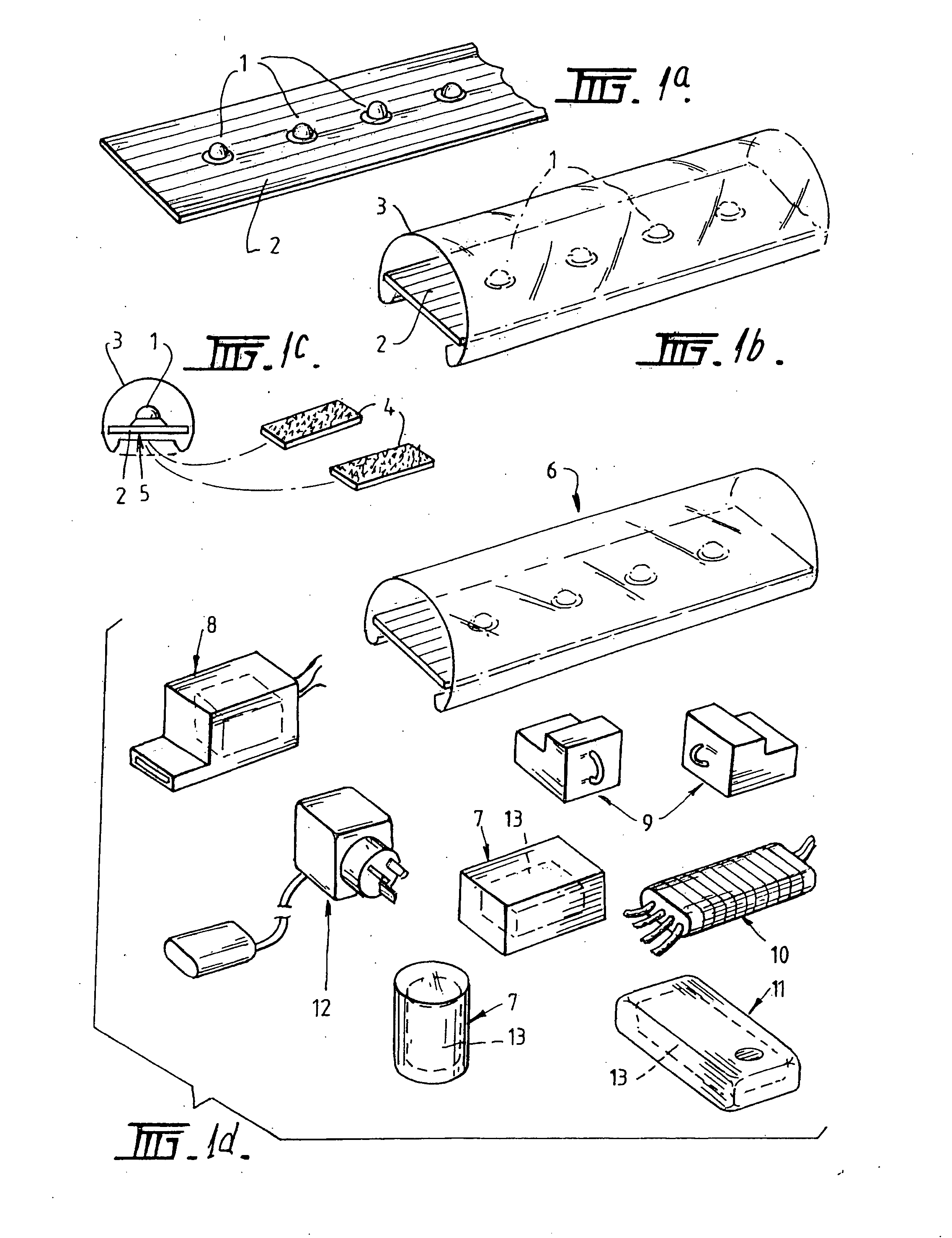
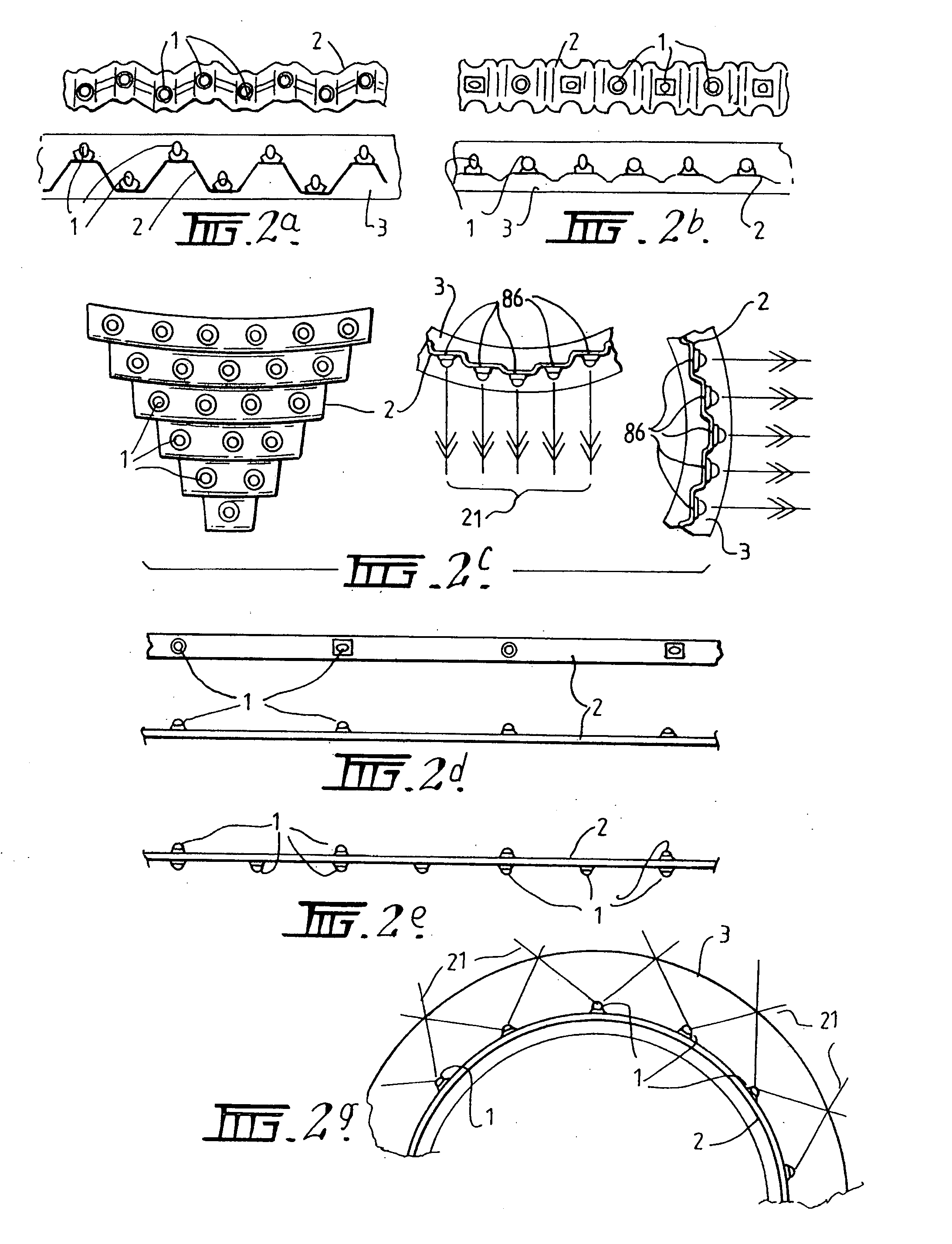
[0039]1. Surface Mounted (SMD) high performance LED's [0040]2. Flexible PCB board mounting selected electronic control components. [0041] Maybe pressed, cut, folded, treated, laminated or any combination to improve flexibility. [0042]3. Protective flexible membrane with outer skin, clear, coloured, or with internal coatings. [0043] Maybe finished to diffuse, direct, colour, fluoresce or otherwise alter the LED's light [0044]4. Possible mounting methods: Magnetic tape, Velcro, double sided tape, Adhesive backing, clip or hook or other means. [0045]5. Possible base profile of cover (3) to allow invisible mounting [0046]6. Basic lineal component of LIGHTFINGER, consists of [0047] (1) LED's [0048] (2) PCB with electric components to suit application [0049] (3) Protective flexible membrane with tough skin. [0050]7...


PUM


Abstract

A visual recognition and identification apparatus comprising a mounting means adapted for placement on an object wherein said mounting means incorporates one or a plurality of light emitting diodes adapted to provide a visual signal characterised in that said LED's are mounted in, on, or connected to a printed circuit board, wherein said printed circuit board is surface modified to provide a distinct angle of mounting for one or a plurality of LED's to provide a highly defined focused viewing angle for said apparatus, wherein said mounting angle results in the focusing of said LED's at a defined focal point.

Description

[0001] This invention relates to the methods and apparatus to visually improve the recognition of individuals, equipment, and define, or identify areas of potential physical danger in poor and very low levels of light. BACKGROUND OF THE INVENTION [0002] There exists a need to assist with the visual identification of people and objects in low levels of ambient light. Emergency workers are often required to work in dangerous conditions where there is no available general light (including sunlight) or extremely low levels of illumination. The current safety methods used to identify people; equipment or hazards rely heavily on the use of reflective materials combined within either their safety clothing or reflective signs, barriers or other light reflective materials. All these items require the application of a light source such as a torch or spotlight beam reflecting light off these special surfaces back to the eyes of an observer. [0003] Portable emergency high performance floodlight...

Claims


Application Information

Patent Timeline
Patent Type & Authority Applications(United States)
IPC IPC(8): F21V21/08F21S4/00F21V21/084F21V5/00F21V21/00A01K11/00A01K27/00A41D13/01A42B1/24A44C3/00B60Q1/32B60Q1/50B60Q1/52B60Q1/56B60Q7/00E01F9/524E01F9/559E01F9/582F21S4/26F21Y115/10G09F9/302G09F13/22G09F19/22G09F21/02G09F23/04H01L27/15H05K1/18
CPCA01K11/00H05K1/189A41D13/01A42B1/248B60Q1/32B60Q1/323B60Q1/503B60Q1/52B60Q1/56B60Q7/00E01F9/044E01F9/065E01F9/085F21S4/007F21V33/0008F21Y2101/02G09F19/22G09F21/02A01K27/006F21S4/26E01F9/582E01F9/524E01F9/559F21Y2115/10B60Q1/324B60Q1/5035
Inventor TRAYNOR, NEIL
Owner TRAYNOR NEIL
Why Eureka
Try Eureka