
Optically pumped semiconductor laser pumped optical parametric oscillator

a semiconductor laser and optical parametric oscillator technology, applied in the direction of optical resonator shape and construction, laser details, instruments, etc., can solve the problems of not developing a commercial diode-pumped ops laser capable of providing fundamental radiation, no readily available diode-laser that can be used for pumping such a structure, and more complex configurations are required to optimize the frequency dividing process

Inactive Publication Date: 2007-12-20
COHERENT INC
View PDF9 Cites 31 Cited by
  • Summary
  • Abstract
  • Description
  • Claims
  • Application Information

AI Technical Summary

Benefits of technology

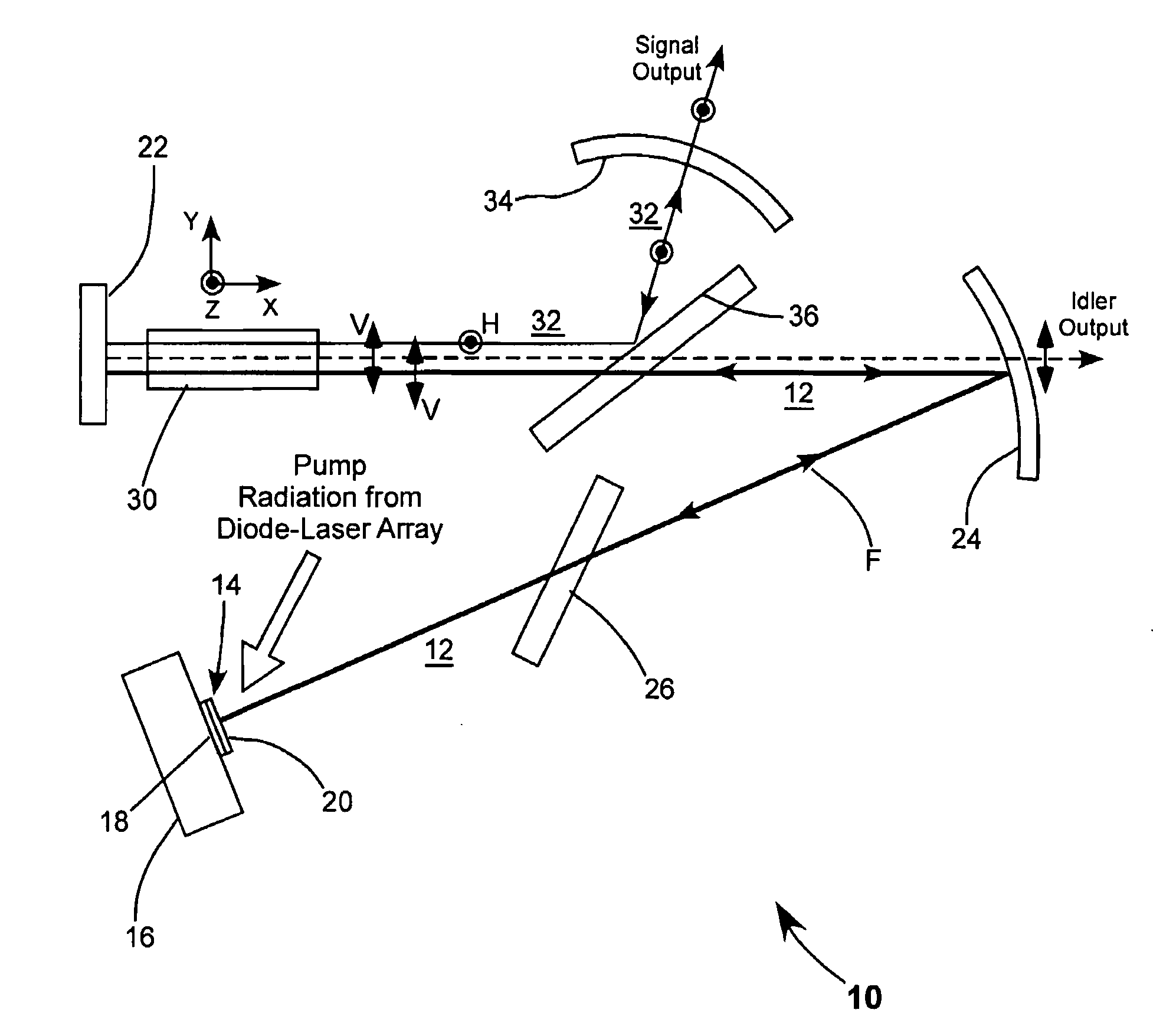
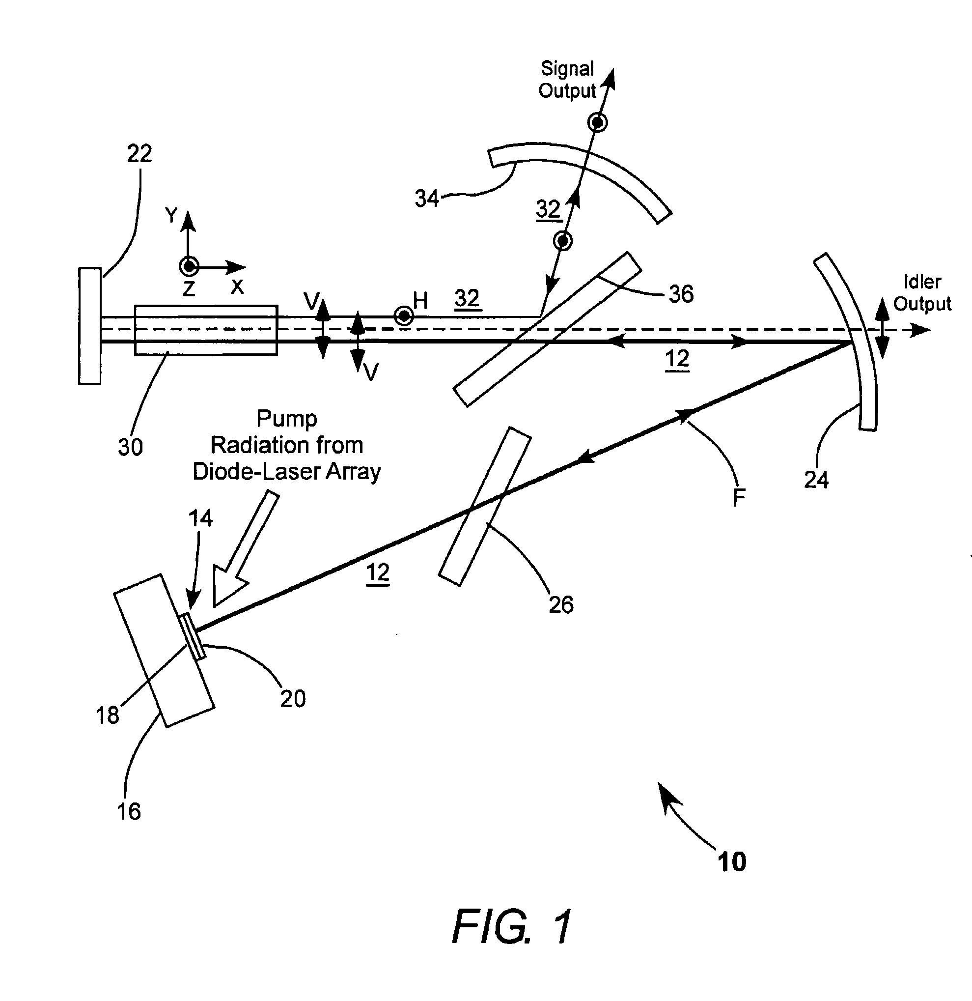
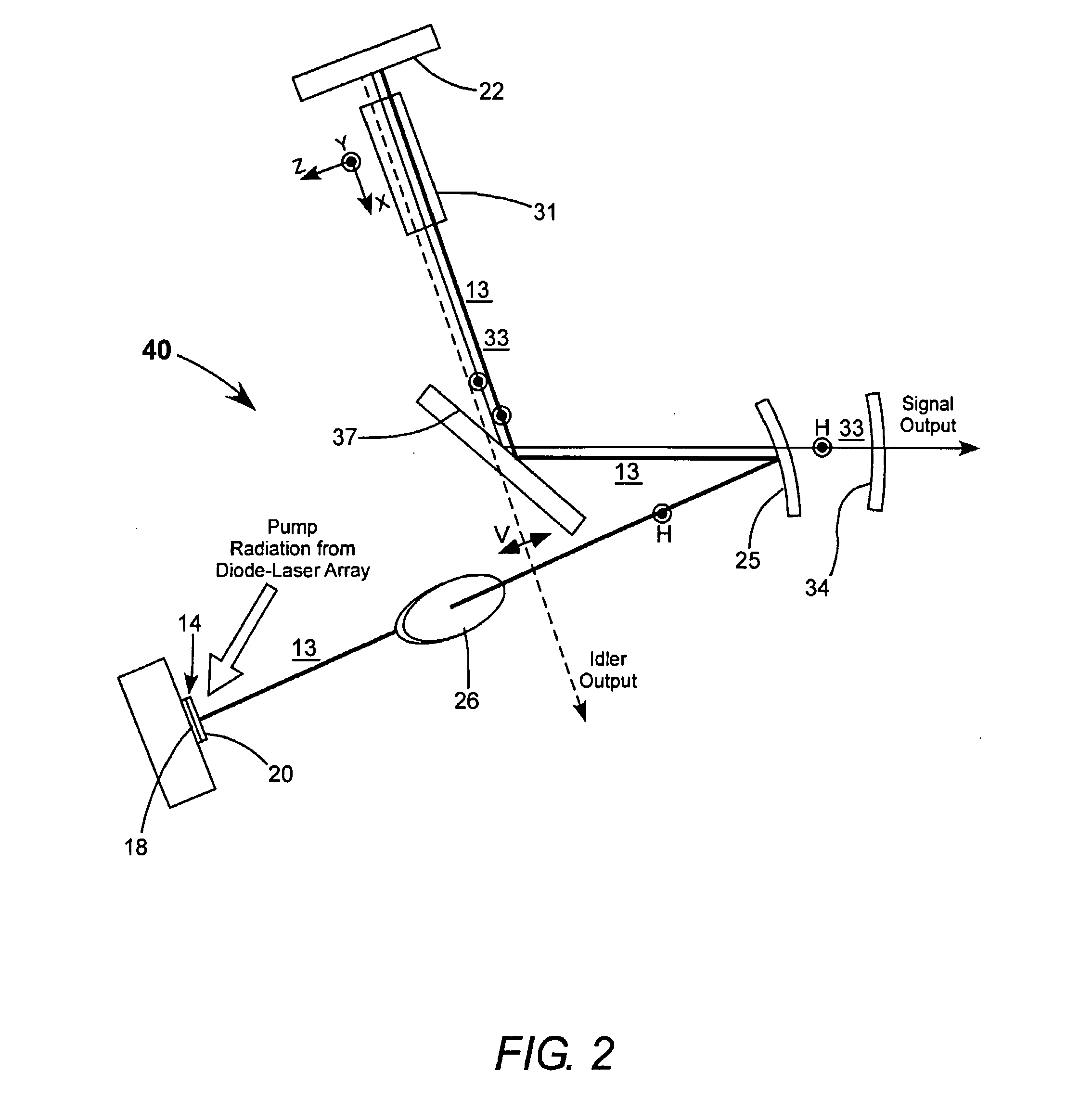
[0007]The present invention is directed to optimizing frequency-division in an OPS-laser-pumped optical parametric oscillator. In one aspect, apparatus in accordance with the present invention comprises, an OPS laser resonator including an OPS-structure. The OPS-structure includes a mirror-structure and a multilayer semiconductor gain-structure. The OPS laser resonator has an OPS resonator axis folded at least once by a fold-mirror. An arrangement is provided for energizing the gain-structure of the OPS-structure of the OPS laser resonator, thereby causing radiation having a fundamental wavelength to circulate in the OPS laser resonator. The apparatus also includes an OPO resonator having an OPO resonator axis folded by a polarizing beamsplitter. A portion of the OPS laser resonator axis and a portion of the OPO resonator axis are coaxial. An optically nonlinear crystal is located in the coaxial portion of the OPS laser and OPO resonators and arranged to frequency divide fundamental radiation generated in the OPS laser resonator.

Problems solved by technology

To date there has not been developed a commercial diode-pumped OPS laser capable of providing fundamental radiation at mid-IR wavelengths, for example, at wavelengths of about 1500 nm and longer.
One possible reason for this is that there are no readily available diode-lasers that can be used for pumping such a structure even were one to be developed.
It is believed that while these OPS-pumped OPO configurations can provide adequate frequency dividing, more complex configurations are required to optimize the frequency dividing process.

Method used


Image

  • Optically pumped semiconductor laser pumped optical parametric oscillator
  • Optically pumped semiconductor laser pumped optical parametric oscillator
  • Optically pumped semiconductor laser pumped optical parametric oscillator

Examples


Embodiment Construction

[0018]Turning now to the drawings, wherein like features are designated by like reference numerals, FIG. 1 schematically illustrates a preferred embodiment 10 laser apparatus in accordance with the present invention. Apparatus 10 includes a fundamental resonator 12 including an OPS (optically pumped semiconductor) structure (chip) 14 on a heat sink 16. Resonator 12 is referred to hereinafter as the OPS-resonator. The OPS-structure includes a mirror-structure 18 surmounted by a semiconductor multilayer gain-structure 20. The OPS-resonator is terminated by mirror-structure 18 of OPS-structure and a plane mirror 22 and folded by a concave dichroic mirror 24, which is highly reflective at the fundamental wavelength.

[0019]Gain-structure 20 of the OPS-structure is continuously energized (pumped) by pump radiation from a diode-laser array (not explicitly shown) causing continuous-wave (CW) fundamental radiation F, depicted in bold line, to circulate in the resonator. The wavelength of the ...


PUM


Abstract

An optically pumped semiconductor pumped optical parametric oscillator (OPS-pumped OPO) includes an OPS laser resonator and an OPO resonator A portion the OPS laser resonator axis and the OPO resonator axis are collinear. An optically nonlinear crystal is located in the coaxial portion of the resonators and arranged to frequency divide fundamental radiation generated in the OPS laser resonator into signal and idler radiations. In one arrangement, the OPO laser resonator is also an OPS resonator and is arranged to generate radiation at the wavelength of the signal radiation, with the idler radiation having the difference-frequency wavelength of the signal and fundamental radiations

Description

PRIORITY CLAIM[0001]This application claims priority of U.S. Provisional Application No. 60 / 814,765, filed Jun. 19, 2006, the complete disclosure of which is hereby incorporated by reference.TECHNICAL FIELD OF THE INVENTION[0002]The present invention relates in general to external cavity optically pumped semiconductor (OPS) lasers. The invention relates in particular to an optical parametric oscillators (OPO) pumped by radiation from an OPS laser.DISCUSSION OF BACKGROUND ART[0003]Diode-pumped OPS lasers are now being increasingly used as an alternative to diode-pumped solid-state lasers. The most common OPS lasers employ gallium-arsenide-substrate (GaAs-substrate) based devices and provide fundamental radiation at a wavelength of about 980 nm or thereabouts. This is a preferred pump wavelength for fiber lasers. This fundamental wavelength can be frequency-doubled to provide radiation having a wavelength of about 490 nm that is useful in optical inspection apparatus and forensic lase...

Claims


Application Information

Patent Timeline
IPC IPC(8): H01S3/10
CPCG02F1/39H01S3/082H01S5/14H01S3/109H01S3/1083
Inventor CAPRARA, ANDREASPINELLI, LUIS A.AUSTIN, R. RUSSEL
Owner COHERENT INC
Learn More