
System and method to start a fuel cell stack during a cold-start condition

a fuel cell and cold-start technology, applied in the field of fuel cell systems, can solve the problems of fuel cell heat generation, very low efficiency of electrochemical reaction process, and inability to start the energy conversion process in a discernable amount of time, and achieve the effect of increasing the battery temperatur

Inactive Publication Date: 2007-12-20
BDF IP HLDG
View PDF4 Cites 74 Cited by
  • Summary
  • Abstract
  • Description
  • Claims
  • Application Information

AI Technical Summary

Benefits of technology

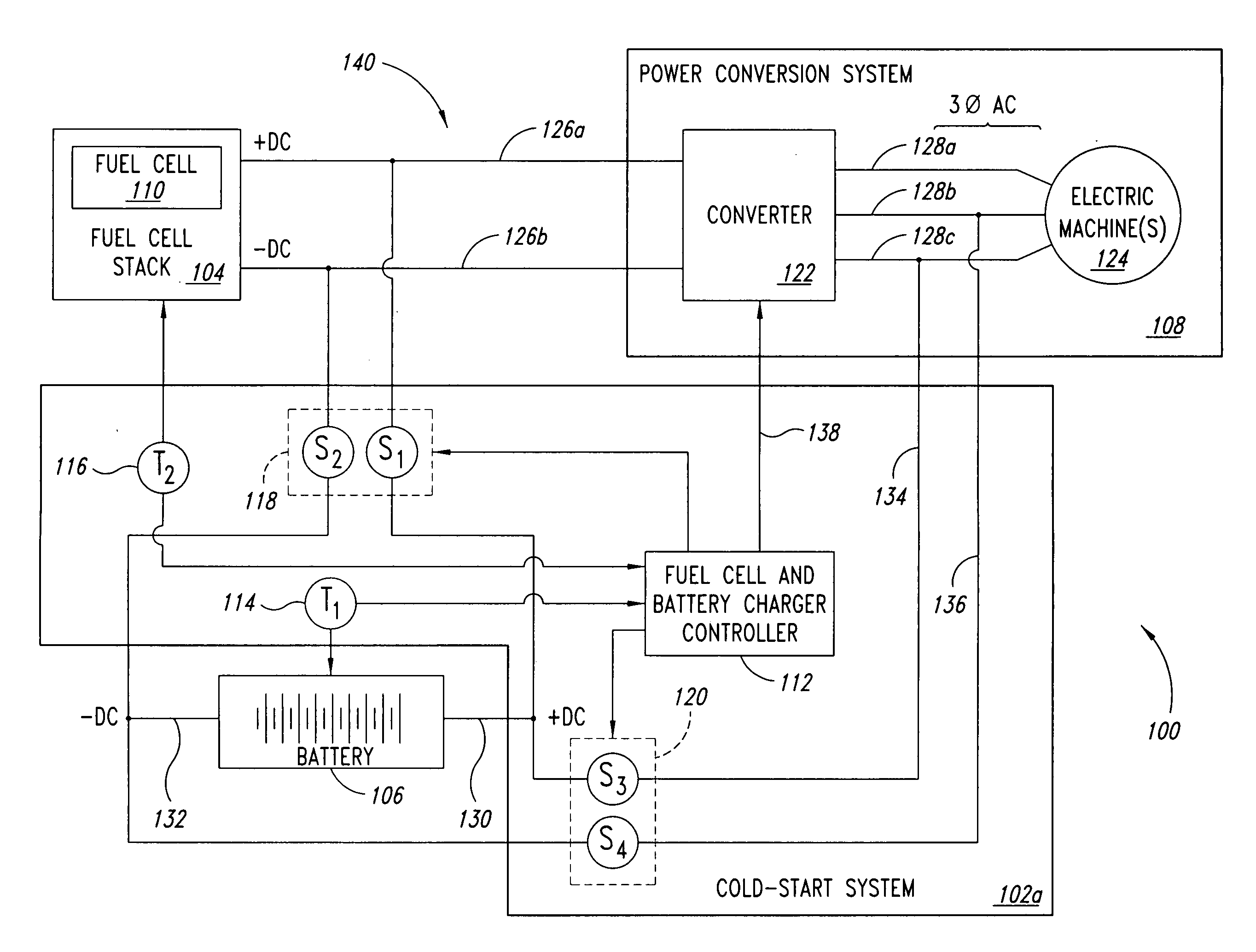
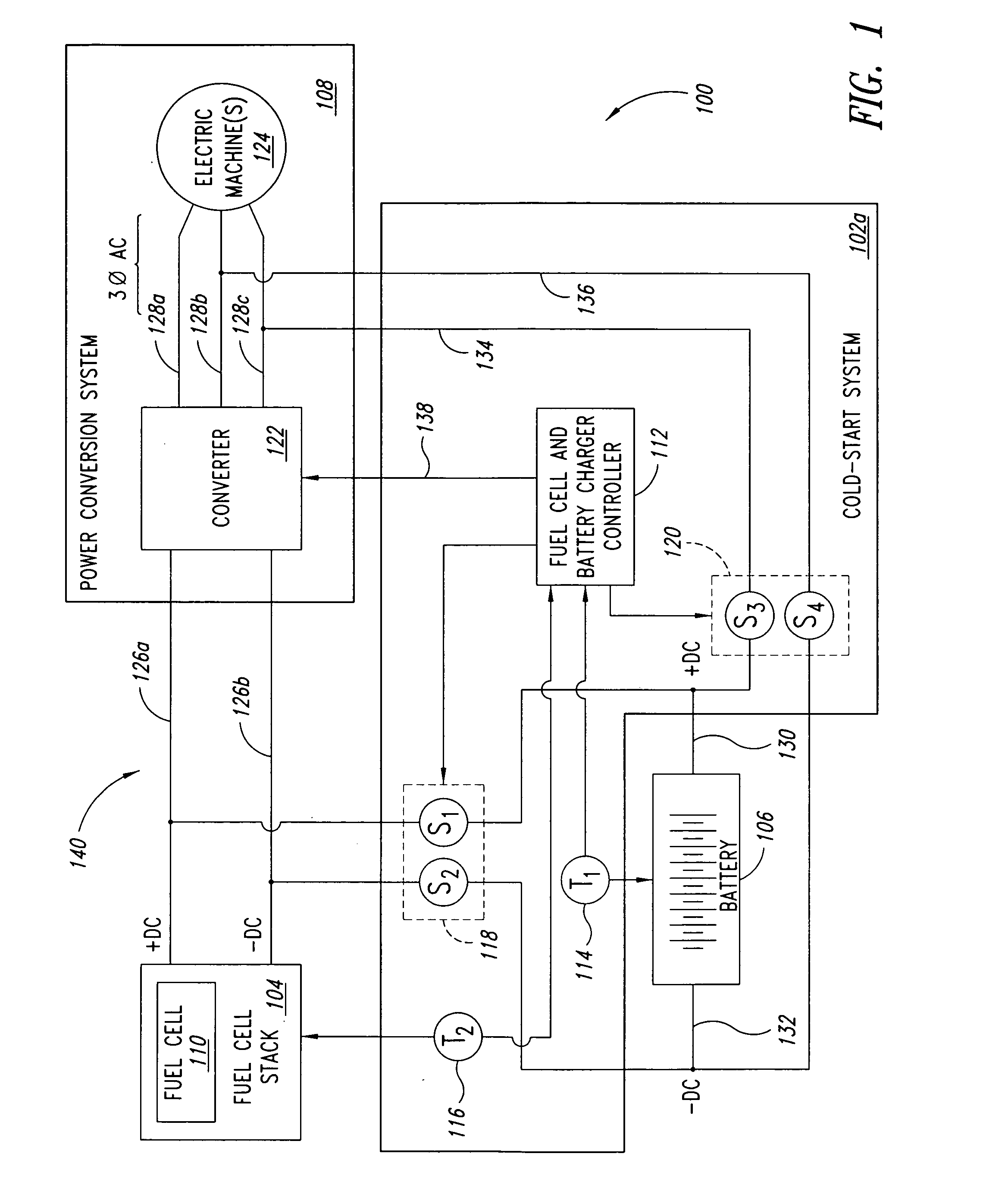
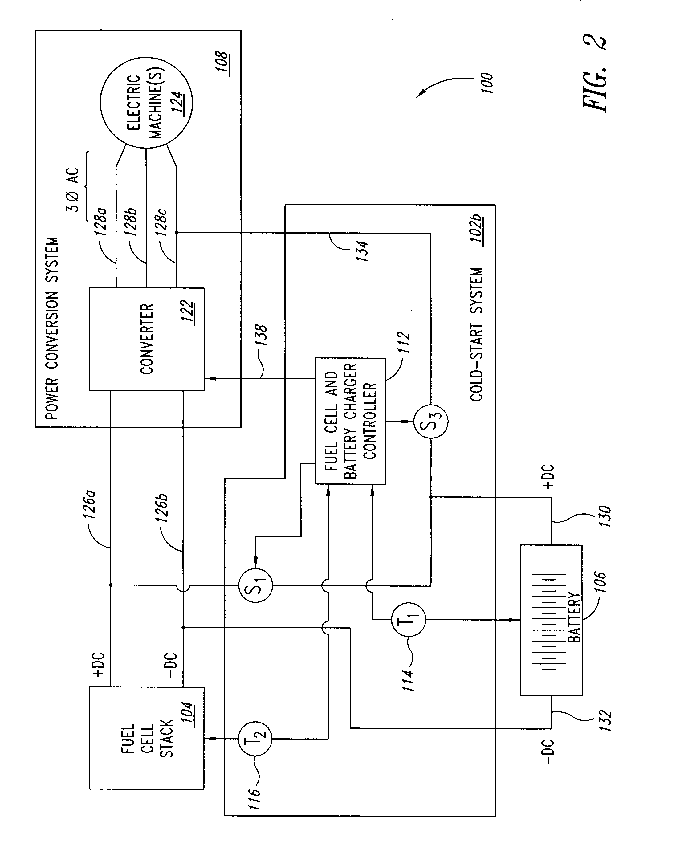
[0017]In another aspect, an embodiment may be summarized as a method for operating a fuel cell stack and at least one battery during at least a cold-start condition, the method comprising receiving direct current from at least one fuel cell of the fuel cell stack during the cold-start condition, converting at least a portion of the received direct current into pulsating current, and providing the pulsating current to the battery during at least a portion of the cold-start condition so that excess heat is generated within the battery during the cold-start condition to increase a temperature of the battery.

Problems solved by technology

That is, the process of initially injecting fuel and / or oxidant into the fuel cell and starting the energy conversion process may take some discernable amount of time as voltage and / or current levels increase up to normal operating conditions.
Cold-start conditions may be significant issues in northern regions of the U.S., Canada, or other areas during the winter months where near-freezing or below-freezing ambient temperatures occur.
During a cold-start condition, the electrochemical reaction process is very electrically inefficient such that relatively low voltage at relatively small current output is available from the fuel cell.
Operating at reduced voltage produces heat for the fuel cells through relatively high internal power losses occurring during reduced voltage operation.
However, when a battery is operated at a cold temperature, battery output current is significantly less than the amount of available output current provided from the battery during normal operating temperatures.
Operating a battery with pulsed current produces heat through relatively high internal power losses.
Power systems using power provided by a fuel cell stack and / or a battery may not become operational until the fuel cell stack and / or battery are capable of providing sufficient power.
From a consumer's point of view, relatively long waits until the electric vehicle may be used are simply unacceptable.

Method used


Image

  • System and method to start a fuel cell stack during a cold-start condition
  • System and method to start a fuel cell stack during a cold-start condition
  • System and method to start a fuel cell stack during a cold-start condition

Examples


Embodiment Construction

[0027]In the following description, certain specific details are set forth in order to provide a thorough understanding of various embodiments. However, one skilled in the art will understand that the invention may be practiced without these details. In other instances, well-known structures associated with power converters, controllers and / or gate drives have not been shown or described in detail to avoid unnecessarily obscuring descriptions of the embodiments.

[0028]Unless the context requires otherwise, throughout the specification and claims which follow, the word “comprise” and variations thereof, such as, “comprises” and “comprising” are to be construed in an open sense, that is as “including, but not limited to.”

[0029]Reference throughout this specification to “one embodiment” or “an embodiment” means that a particular feature, structure or characteristic described in connection with the embodiment is included in at least one embodiment. Thus, the appearances of the phrases “i...


PUM


Abstract

A system and method for operating a fuel cell stack and at least one battery during at least a cold-start condition includes operating a fuel cell stack at a reduced voltage during the cold-start condition, and / or sourcing pulsating current to a battery during the cold-start condition.

Description

BACKGROUND OF THE INVENTION[0001]1. Field of the Invention[0002]This disclosure generally relates to electrical power systems, and more particularly to fuel cell systems.[0003]2. Description of the Related Art[0004]Electrochemical fuel cells convert reactants, namely fuel and oxidant fluid streams, to generate electric power and reaction products. Electrochemical fuel cells generally employ an electrolyte disposed between two electrodes, namely a cathode and an anode. An electrocatalyst, disposed at the interfaces between the electrolyte and the electrodes, typically induces the desired electrochemical reactions at the electrodes.[0005]In a fuel cell stack, a plurality of fuel cells are connected together, typically in series, to increase the overall output power of the assembly. During normal operation of a fuel cell stack, fuel is electrochemically reduced on the anode side, typically to generate protons, electrons, and possibly other species depending on the fuel employed. The pr...

Claims


Application Information

Patent Timeline
IPC IPC(8): H01M16/00H01M8/04H02J7/00H01M10/50
CPCH01M8/04007H01M10/5026H01M8/0432H01M8/04365H01M8/04373H01M8/04731H01M8/04738H01M8/0488H01M8/04917H01M8/04955H01M10/486H01M16/006Y02E60/50H01M10/5006H01M8/04268H01M10/615H01M10/637Y02E60/10
Inventor GILCHRIST, IAN T.
Owner BDF IP HLDG
Learn More