Integrated mass air flow sensor and broadband silencer

a mass air flow sensor and broadband technology, applied in the direction of electrical control, instruments, furniture, etc., can solve the problems of exacerbated low flow rate turbulence and its attendant adverse impact on mafs output, the typical signal-to-noise ratio of air turbulence, and the inability to detect the effect of air turbulence on the mass air flow sensor. achieve the effect of reducing the intensity of high frequency vibration and reducing the intensity of low frequency vibration

Inactive Publication Date: 2007-12-20
MANN HUMMEL GMBH
View PDF3 Cites 27 Cited by
  • Summary
  • Abstract
  • Description
  • Claims
  • Application Information

AI Technical Summary

Benefits of technology

[0014]According to one embodiment, the perforations are sized and spaced to reduce the intensity of low frequency vibrations emitted from the upstream segment. According to a further embodiment, the plurality of rings are sized and spaced to reduce the intensity of high frequency vibrations emitted from the downstream segment. Advantageously, the mass air flow sensor is located within the mass air flow sensor flow tube.

Problems solved by technology

Because the output signal, and in particular the signal-to-noise ratio of a typical mass air flow sensor can be adversely affected by air turbulence, mass air flow sensors preferably measure air flow having uniform velocity and minimal turbulence over the complete range of engine operating conditions.
The effect of air turbulence on a mass air flow sensor can be particularly problematic under conditions of low flow rate such as during engine idling.
Moreover, low flow rate turbulence and its attendant adverse impact on MAFS output can be exacerbated if the MAFS is located in a relatively large diameter flow path.
The space available for components such as mass air flow sensors and broadband silencers is typically limited due to design and esthetic considerations.
Furthermore, the high flow rates required by many high performance engines are at odds with the low turbulence requirements of mass air flow sensors that are included in these engines.

Method used


Image

  • Integrated mass air flow sensor and broadband silencer
  • Integrated mass air flow sensor and broadband silencer
  • Integrated mass air flow sensor and broadband silencer

Examples


Embodiment Construction

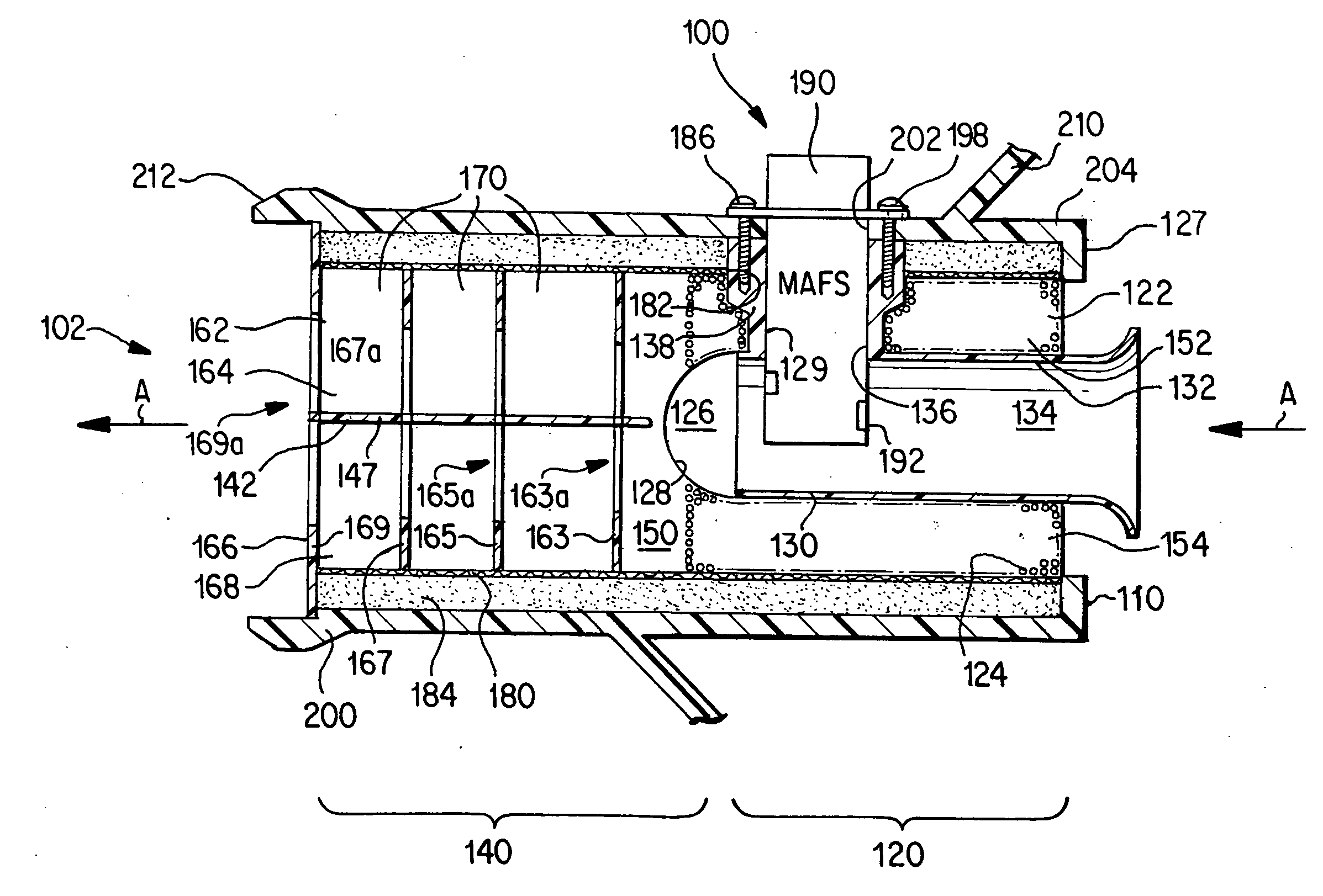
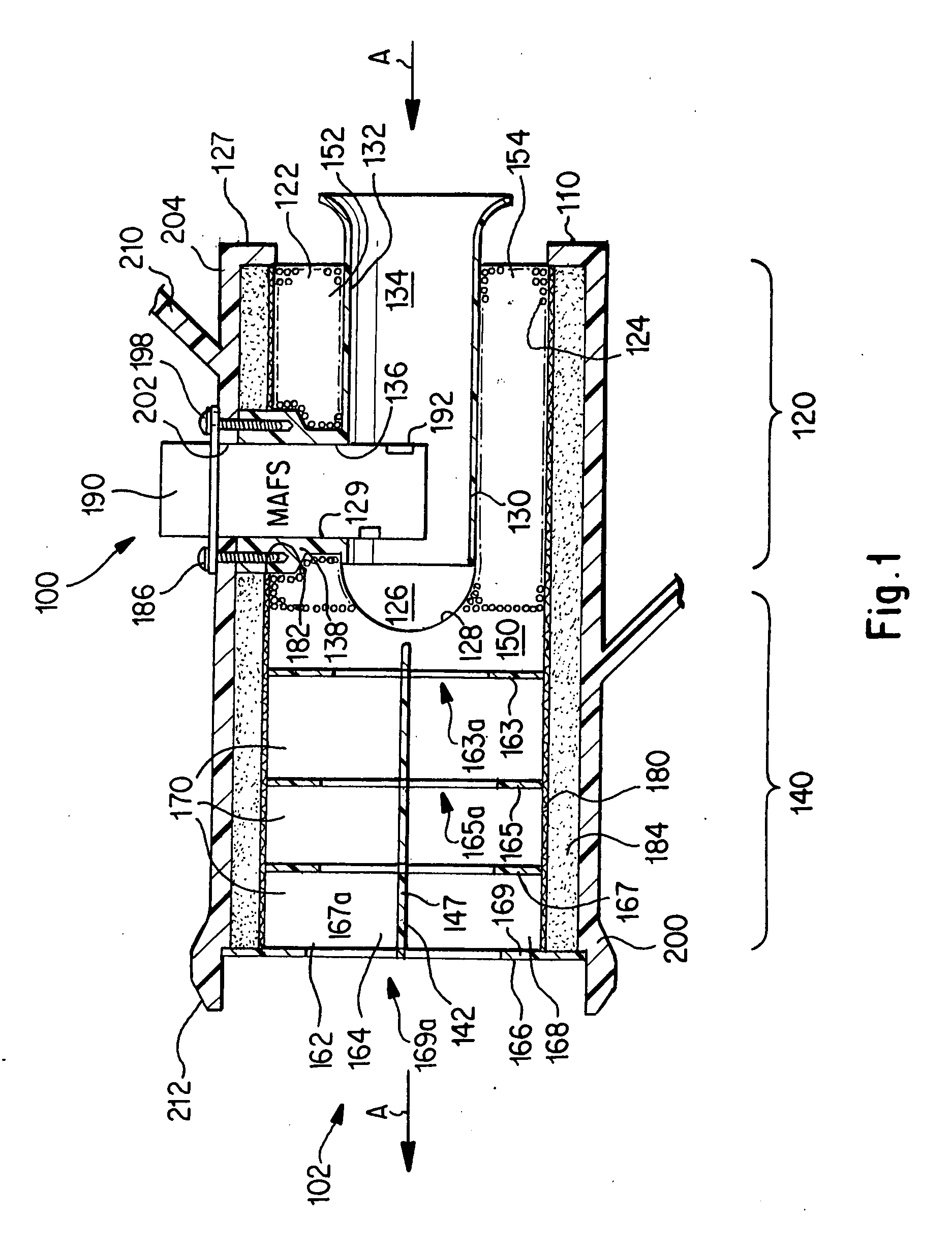
[0021]Referring to FIG. 1, shown is a cross-sectional illustration of an integrated mass air flow sensor / broadband silencer assembly according to a first embodiment. The assembly 100 includes a pre-assembly 102 comprising a molded body 110, a layer of wire mesh 180 and a layer of acoustic foam 184. The wire mesh and acoustic foam are wrapped over an outer circumferential periphery of the molded body and define a pre-assembly having a substantially cylindrical shape. A perspective view of pre-assembly 102 is shown in FIG. 3.

[0022]The molded body, which is preferably a unitary part, comprises a plurality of walls, a mass air flow sensor flow tube 130, and an optional pair of fastener receiving portions 138. The molded body is divided into an upstream segment 120 and a downstream segment 140. In one embodiment, the length of the upstream segment 120 is preferably approximately equal to the length of the downstream segment 140.

[0023]The wire mesh, which provides support for the layer of...


PUM


Abstract

An integrated mass air flow sensor/broadband silencer assembly comprises a molded body having a plurality of walls formed therein. The molded body is over-wrapped with a layer of acoustic foam that, together with the plurality of walls, define a plurality of chambers within an interior volume of the assembly. A mass air flow sensor can be inserted into one of the chambers. The chambers are sized and spaced to provide a uniform velocity, low turbulence air flow to the sensor, and a minimally-restricted air flow to an internal combustion engine located downstream of the assembly.

Description

BACKGROUND OF THE INVENTION[0001]The invention relates to an assembly comprising an integrated mass air flow sensor and a broadband silencer that is adapted for use in the air induction system of an internal combustion engine.[0002]In many internal combustion engines, a mass air flow sensor (MAFS) is used to measure the air flow rate entering the engine and, in turn, provide an output signal that is used to maintain a desired air-fuel ratio. Maintaining a desired air-fuel ratio is important to achieve optimal engine performance, fuel economy, and engine emissions.[0003]Because the output signal, and in particular the signal-to-noise ratio of a typical mass air flow sensor can be adversely affected by air turbulence, mass air flow sensors preferably measure air flow having uniform velocity and minimal turbulence over the complete range of engine operating conditions.[0004]The effect of air turbulence on a mass air flow sensor can be particularly problematic under conditions of low fl...

Claims


Application Information

Patent Timeline
Patent Type & Authority Applications(United States)
IPC IPC(8): F27D17/00
CPCF02M35/021F02M35/10386F02M35/14G01F1/684F02M35/1277G01F5/00F02D41/18F02M35/1211F02M35/1272G01F1/72
Inventor MILLER, STUART
Owner MANN HUMMEL GMBH
Why Eureka
Try Eureka