Geothermal Exchange System Using A Thermally Superconducting Medium With A Refrigerant Loop

a technology of thermal superconducting medium and refrigerant loop, which is applied in the direction of solar heat devices, other heat production devices, lighting and heating apparatus, etc., can solve the problems of low penetration rate of consumer markets, high capital and installation costs, and relatively high cost, so as to reduce the installation cost of ground loops and prolong the life. , the effect of enhancing cooling and heating efficiency

Inactive Publication Date: 2007-12-27
FREE ENERGY SOLUTIONS
View PDF16 Cites 60 Cited by
  • Summary
  • Abstract
  • Description
  • Claims
  • Application Information

AI Technical Summary

Problems solved by technology

Even though ground source heat pump systems achieve efficiencies of up to 350% compared to less than 100% for many conventional systems, they have been slow to penetrate the consumer marketplace because of high capital costs, high installation costs, difficult installation procedures and low energy cost savings due to historically low energy prices.
These high capital and installation costs have largely been due to fundamental inefficiencies in the ground loop subsystem.
Few installations have sufficient available land for trenching so loops are most commonly installed in deep holes and this makes them relatively expensive for several reasons.
Holes of this size are relatively expensive to drill and require heavy equipment that disrupts landscaping, making it expensive to retrofit existing homes.
Holes of this size also leave large voids around the loop that should be filled with materials such as bentonite clay in order for heat to transfer from the ground to the loop, which adds significantly to the cost of installation.
Second, having both supply and return lines in the same hole results in thermal “short circuiting” which reduces the efficiency of the loop.
This lowers the efficiency of the loop so the loop should be made longer to compensate, adding to the cost of drilling and piping.
This consumes a significant amount of electric energy, lowering the overall efficiency of the system.
Third, the copper pipes used in direct geoexchange transfer heat more efficiently to and from the ground so the total length of loop required is typically less than conventional systems.
First, both supply and return pipes run in the same hole, so the thermal short circuit problems of conventional systems remain.
Second, the loop system pumps much more refrigerant through many more feet of piping past many more connections than conventional systems, so the potential for refrigerant leaks is increased.
Third, direct geoexchange requires large volumes of refrigerant to flow through the loop, behaving differently in the heating and cooling modes, and requiring additional refrigerant reservoirs and flow control systems to compensate.
Because of these inefficiencies, direct geoexchange is only able to achieve a modest improvement in total energy efficiency over conventional ground source heat pump systems.
Direct geoexchange and conventional ground source heat pump systems have additional limitations.
Both require a significant amount of electrical power to pump fluids through hundreds or thousands of feet of piping.
This not only limits overall system efficiency but also limits the environments in which it can be installed.
This kind of power is not often available or reliable in the world's developing countries, so existing ground source heat pump systems have limited potential to penetrate broad world markets.
In addition, since both systems are designed to heat and cool whole buildings, neither can efficiently be installed on the incremental room-by-room basis on which most of the world adopts heating and air conditioning.
In summary, conventional geoexchange systems and direct expansion geoexchange systems have significant limitations in energy efficiency, installation cost and installation flexibility.

Method used


Image

  • Geothermal Exchange System Using A Thermally Superconducting Medium With A Refrigerant Loop
  • Geothermal Exchange System Using A Thermally Superconducting Medium With A Refrigerant Loop
  • Geothermal Exchange System Using A Thermally Superconducting Medium With A Refrigerant Loop

Examples


Embodiment Construction

)

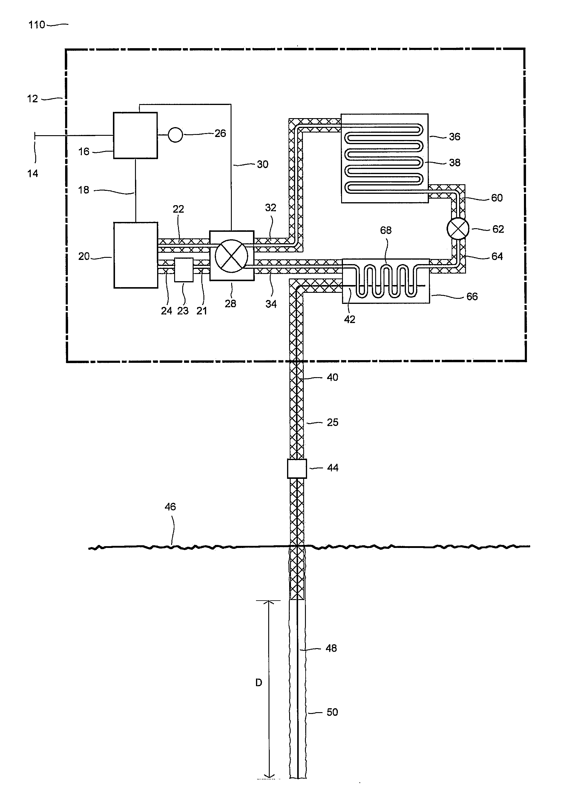
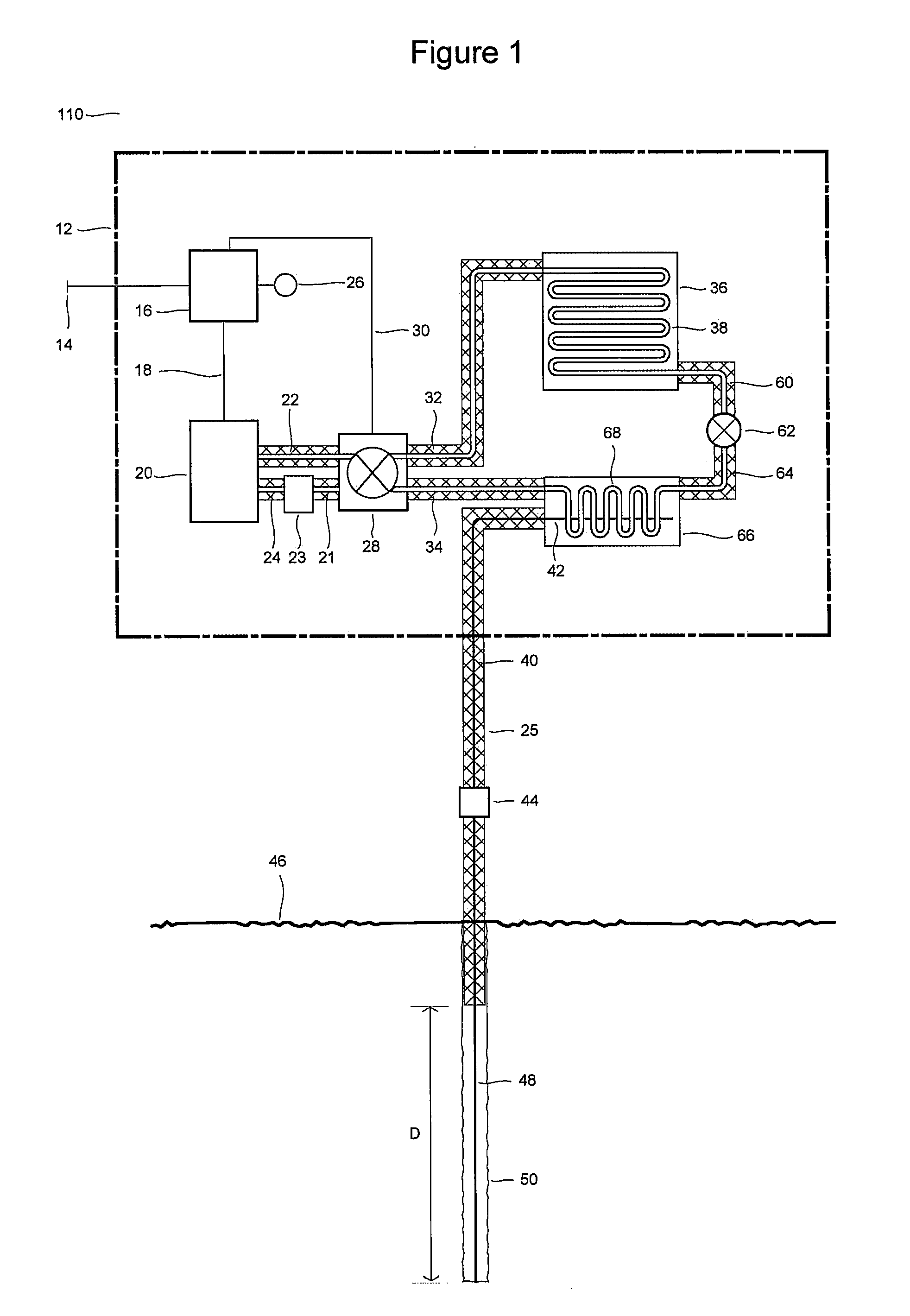
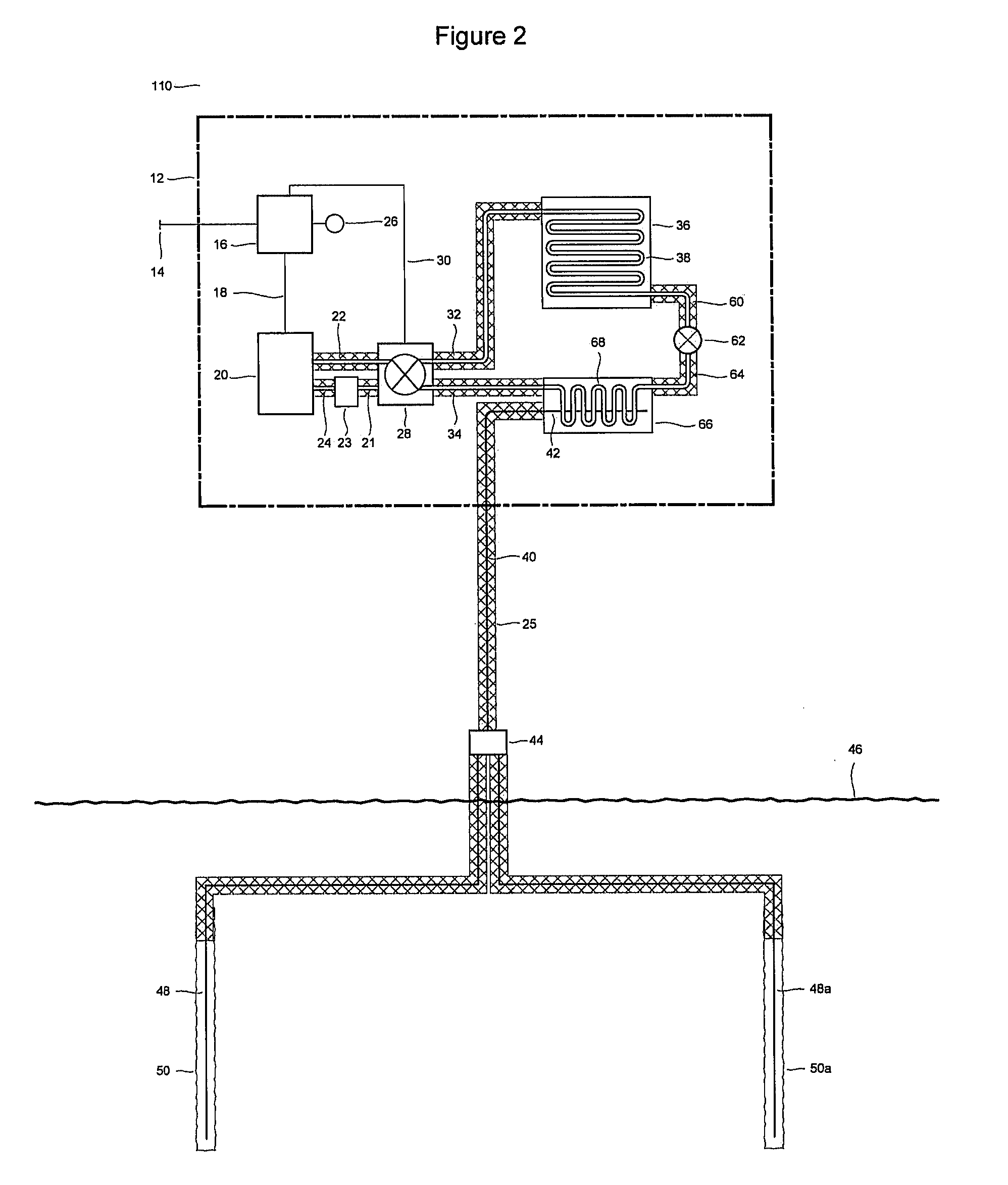
[0042] With reference to the drawings, new and improved heating and cooling devices and geothermal exchange systems embodying the principles and concepts of the present device will be described. In particular, the devices and systems are applicable for climate control within structures as well as more generally to bi-directional heat transfer to and from earth sources. The embodiments shown in the attached figures satisfy the need for a geothermal exchange system with improved thermal efficiency, lower installation cost and greater installation flexibility.

[0043] Recent advances in thermal superconducting materials can now be considered for use in novel energy transfer applications. For example, U.S. Pat. No. 6,132,823 and continuations thereof, discloses an example of a heat transfer medium with extremely high thermal conductivity, and is included herein by reference. Specifically the following disclosure indicates the orders of magnitude improvement in thermal conduction; “Exper...


PUM

PropertyMeasurementUnit
diameteraaaaaaaaaa
poweraaaaaaaaaa
poweraaaaaaaaaa

Abstract

A geothermal exchange system is couplable to a ground coil formed from a thermal superconductor material, and transfers heat using a refrigerant loop. The device includes a compressor, a reversible refrigerant loop with two heat exchangers, one of which couplable to a thermal superconductor ground loop. The device uses a high thermal transfer superconductor to efficiently move heat to and from the earth source for the purpose of heating and cooling. The device operates in cooling or heating modes by controlling the thermal switches and activating the heat intensification circuit in response to the difference between a set point and a measured temperature. Alternatively, the system can be configured for heating only or cooling only modes, by operating the refrigerant loop in one direction.

Description

FIELD OF THE INVENTION [0001] The present invention relates generally to geothermal cooling systems, and more particularly to a geothermal cooling device coupled with a superconducting heat transfer element for use as an air conditioner. BACKGROUND OF THE INVENTION [0002] Ground source heat pump systems, also known geothermal or geoexchange systems, have been used for heating and cooling buildings for more than half a century. In 1993, the Environmental Protection Agency evaluated all available heating and cooling technologies and concluded that ground source heat pump systems were the most energy efficient systems available in the consumer marketplace. [0003] Conventional ground source heat pump systems operate on a simple principle. In the heating mode they collect heat energy from the ground and transfer it to a heat pump, which concentrates the heat and transfers it to a building's heat distribution system which in turn heats the building. In the cooling mode, heat from the buil...

Claims


Application Information

Patent Timeline
Patent Type & Authority Applications(United States)
IPC IPC(8): F24J3/08F25B30/00
CPCF24J3/08F25B13/00F25B30/06Y02E10/10F28D15/0266F28F13/18F28F21/089F25B2313/002F24T10/40
Inventor MUELLER, LYNNGRAHAM, JOHNTODD, DAVID
Owner FREE ENERGY SOLUTIONS
Why Eureka
Try Eureka