Light-Emitting Device

a light-emitting device and light-emitting technology, which is applied in the direction of solid-state devices, electric lighting sources, electric light sources, etc., can solve the problems of cumbersome current adjustment in order to adjust the emitted light level of each color, lack of color rendering properties, poor red components, etc., to achieve good assembly workability, improve color rendering properties when emitting white light, and simplify various adjustment operations

Inactive Publication Date: 2007-12-27
SANYO ELECTRIC CO LTD +1
View PDF7 Cites 74 Cited by
  • Summary
  • Abstract
  • Description
  • Claims
  • Application Information

AI Technical Summary

Benefits of technology

[0037] According to the present invention, features can be provided which can simplify the various adjustment operations of a plurality of light-emitting diodes; a device configuration can be provided which has good assembly workability; color rendering properties when emitting white light can be increased; and, a form can be provided which is convertible with related-art two-terminal light-emitting devices, even when mixing a plurality of colors.

Problems solved by technology

Generally, although devices which emit pseudo-white light by combining a blue light emitting object as the light-emitting device and a yellow light emitting object as the fluorescent body are commonly employed, there is a problem that color rendering properties are lacking as a result of a specific color component being poor (in this case, blue and yellow are mixed, so that the red component is poor).
However, in the case of emitting white light by mixing the three primary colors, the current adjustment in order to adjust the emitted light level of each of the colors is cumbersome.
Not just when emitting white light, but also in the case of obtaining a desired color or emitted light intensity distribution using a plurality of light-emitting diodes which are the same or different color, the current adjustment in order to adjust the emitted light intensity for each of the light-emitting diodes is cumbersome.
While the adjustment can be performed with an external circuit, if an external circuit is provided for each of the individual devices, the circuit configuration becomes complicated.

Method used


Image

  • Light-Emitting Device
  • Light-Emitting Device
  • Light-Emitting Device

Examples


first embodiment

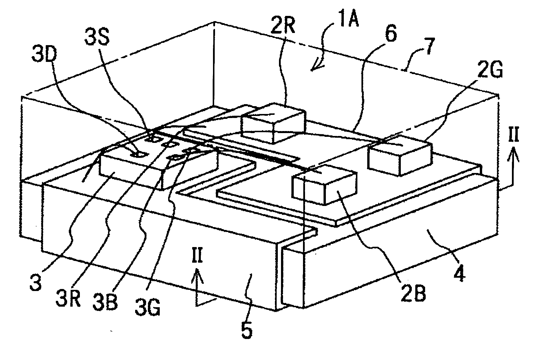
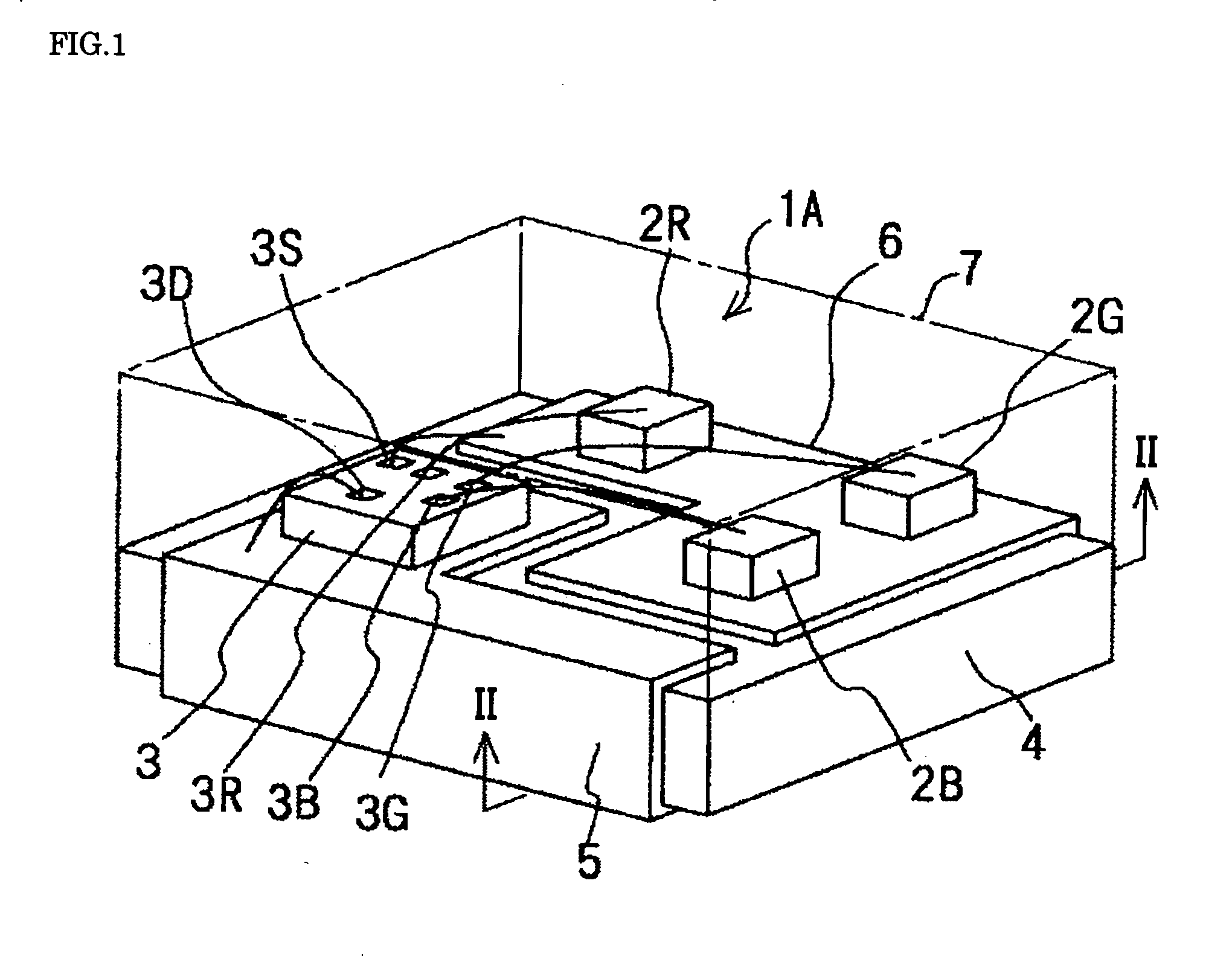
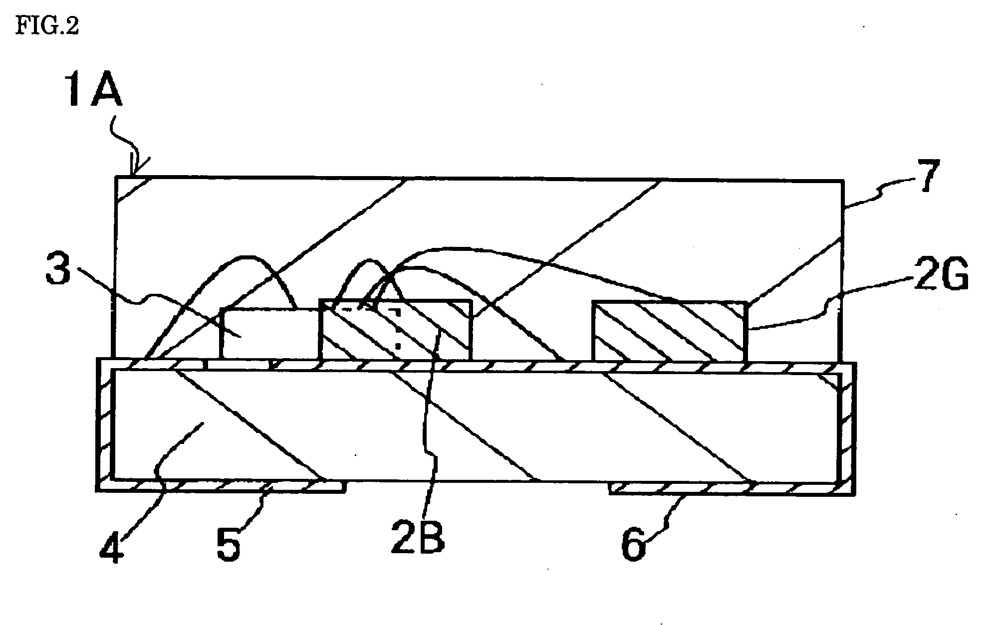
[0093] First, a light-emitting device LA will be described with reference to FIGS. 1 to 5. FIG. 1 is a perspective view as seen through the molded resin of light-emitting device 1A; FIG. 2 is a cross-sectional view taken along the line II-II of FIG. 1; FIG. 3A is a circuit diagram of the light-emitting device 1A; FIG. 3B is an equivalent circuit schematic; FIG. 4 is a detailed circuit diagram of the light-emitting device 1A; and FIG. 5 is a timing chart illustrating the operation of the light-emitting device 1A.

[0094] The light-emitting device 1A is configured such that a plurality of chip-state light-emitting diodes 2 and a drive IC 3 for driving these light-emitting diodes 2 are integrated on a circuit board 4. The light-emitting diodes 2 are configured from bare chips which have been cut-out from a wafer, and comprise three light-emitting diodes 2R, 2G and 2B which have emitted colors of the three primary colors of red (R), green (G) and blue (B) in order to emit white light.

[0...

third embodiment

[0108] Next, a light-emitting device 1C will be described with reference to FIGS. 8 and 9. FIG. 8 is a perspective view as seen through the molded resin of light-emitting device 1C; and FIG. 9 is a cross-sectional view taken along the line IX-IX of FIG. 8.

[0109] The major difference between the light-emitting device 1C according to the third embodiment and the light-emitting device 1A of the first embodiment is that the light-emitting diodes 2 disposed on the circuit board 4 are disposed on the drive IC 3 (the other features basically being the same). The drive IC 3 is fixed by an insulating material or a conductive material on the circuit board 4, and is electrically connected with the external terminals 5, 6 by a wire. In the present embodiment, the drive IC 3 is fixed on an insulating base material of the circuit board 4. The cathode side of the light-emitting diodes 2R, 2G and 2B is fixed by a conductive material onto the terminal for the cathode formed on the surface of the dr...

fifth embodiment

[0115] Next, a fifth light-emitting device 1E will be described with reference to FIGS. 12 to 14. FIG. 12 is a perspective view of the light-emitting device 1E ; FIG. 13 is a cross-sectional view taken along the line XIII-XIII of FIG. 12; and FIG. 14 is a perspective view illustrating the placement of the light-emitting diodes and the drive IC shown in FIG. 13.

[0116] The light-emitting diodes of the first to fourth embodiments have a top view structure wherein light is extracted in a perpendicular direction to the board on which the light-emitting devices 1A to 1D are attached. In contrast, the fifth embodiment has different basic features, in that the light-emitting device 1E has a side view structure wherein light is extracted in a parallel direction to the board on which the light-emitting device 1E is attached. The circuit board 4 of this embodiment has the same structure as the lead frame type board light-emitting device 1 according to the second embodiment, wherein a lead fram...


PUM


Abstract

A light-emitting device (1) is composed by integrating light-emitting diodes (2R, 2G, 2B) and a drive IC (3) for driving these light-emitting diodes (2R, 2G, 2B). The light-emitting device (1) is characterized in that the drive IC (3) has a built-in circuit for controlling the current value of each light-emitting diode (2) or the current proportions of the light-emitting diodes at constant values. The adjustment of the intensities of the light beams emitted from the light-emitting diodes can be simplified, and no outside circuits for adjustment are needed. The structure is excellent in assemblability. When a desired emission color is produced by mixing the emission colors, the adjustment for the mixing is easy, and a structure suited for enhancing the color rendering properties when a while light is emitted is provided.

Description

FIELD OF THE INVENTION [0001] The present invention relates to a light-emitting device which integrally comprises a light-emitting diode with a drive IC thereof. RELATED ART [0002] JP-2001-217463-A discloses a light-emitting device capable of emitting pseudo-white light by combining a light-emitting diode and a fluorescent body which emits light of a complementary color to that of the light-emitting diode. Generally, although devices which emit pseudo-white light by combining a blue light emitting object as the light-emitting device and a yellow light emitting object as the fluorescent body are commonly employed, there is a problem that color rendering properties are lacking as a result of a specific color component being poor (in this case, blue and yellow are mixed, so that the red component is poor). [0003] There are examples which use mixed colors from light-emitting diodes of the three primary colors red, green and blue. However, in the case of emitting white light by mixing th...

Claims


Application Information

Patent Timeline
Patent Type & Authority Applications(United States)
IPC IPC(8): H01L33/00
CPCH01L25/0753H01L25/167H05B33/0818H05B33/0821H05B33/0857H05B33/0866H01L2224/48137H01L2224/45144H01L2924/1305H01L2924/13091H01L2224/48091H01L2924/00014H01L2924/00H01L2924/181H05B45/40H05B45/24H05B45/20H05B45/37H01L2924/00012
Inventor OMAE, MITSUHIRO
Owner SANYO ELECTRIC CO LTD
Why Eureka
Try Eureka