Magnetron

a magnetron and entanglement technology, applied in the field of magnets, can solve the problems of increasing the cost of magnetron and the inability to avoid the increase of the cost due to enlarging, and achieve the effect of improving the efficiency of oscillation outpu

Inactive Publication Date: 2007-12-27
TOSHIBA HOKUTO ELECTRONICS CORP
View PDF10 Cites 7 Cited by
  • Summary
  • Abstract
  • Description
  • Claims
  • Application Information

AI Technical Summary

Benefits of technology

[0019] In accordance with the present invention, improvement of the oscillation output efficiency without enlarging the whole body including the permanent magnets with respect to a magnetron can be put into practice.

Problems solved by technology

However, there is a problem that leads to raising the cost of magnetron because the permanent magnet requires to be enlarged or highly performed and the withstand voltage of the driving circuit is necessary to be high to cope with a high voltage.
However, rise of the cost due to enlarging cannot be evaded because it is necessary for the magnetic flux density Bg in the interaction space to be more enlarged to improve the oscillation output efficiency.

Method used


Image

  • Magnetron
  • Magnetron
  • Magnetron

Examples


Embodiment Construction

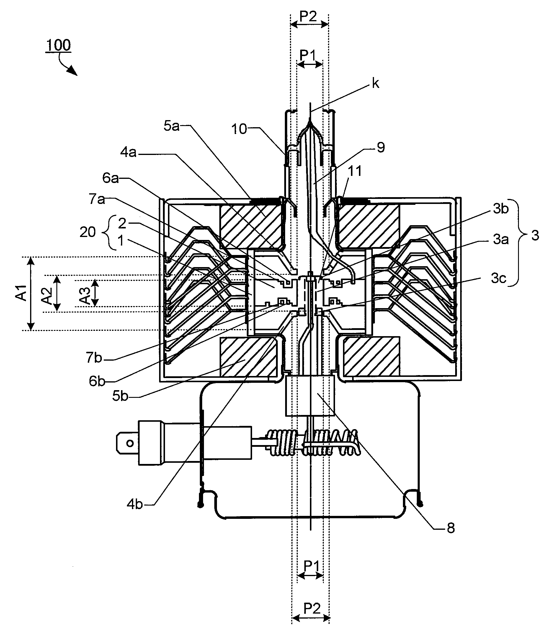
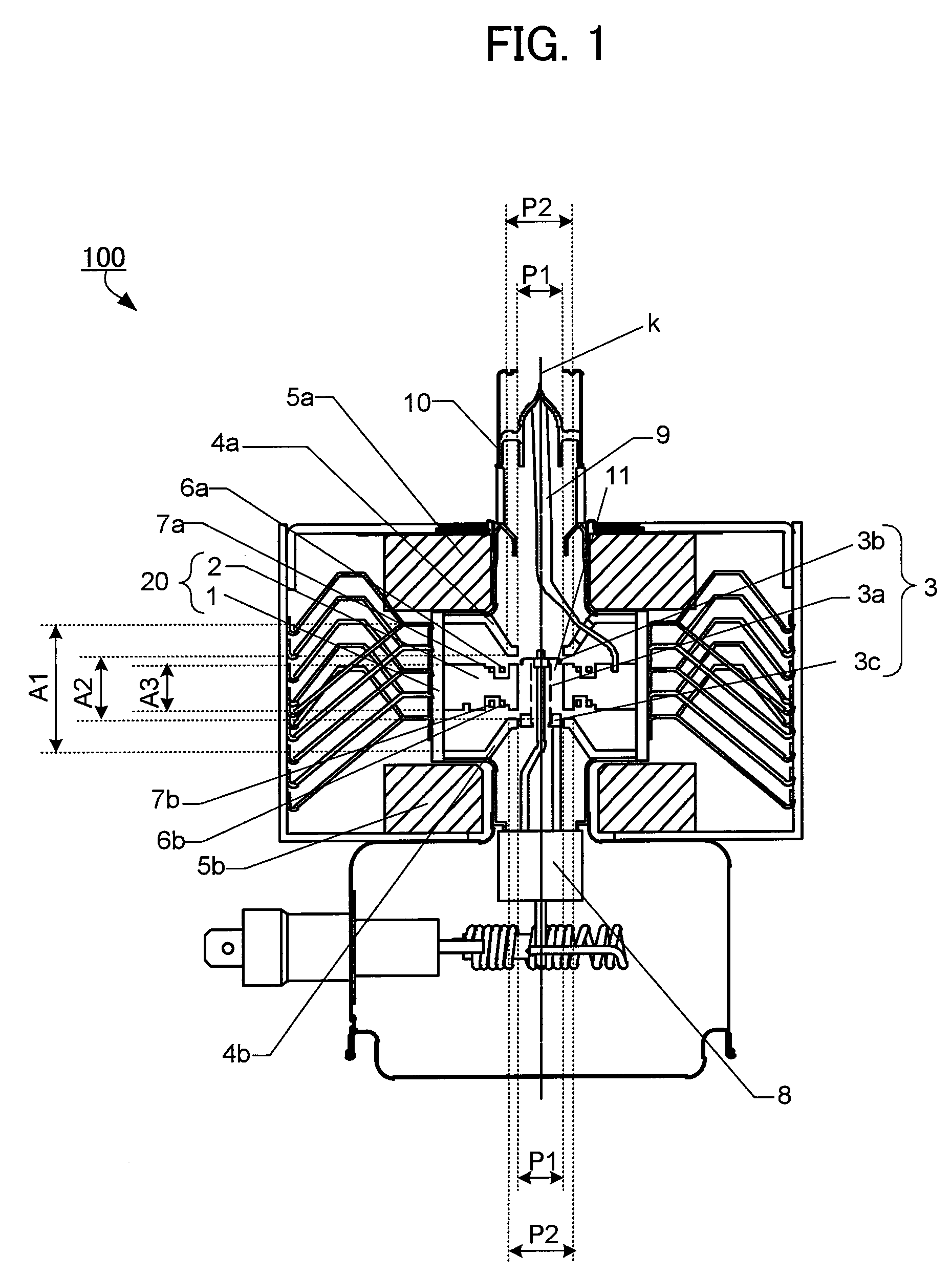
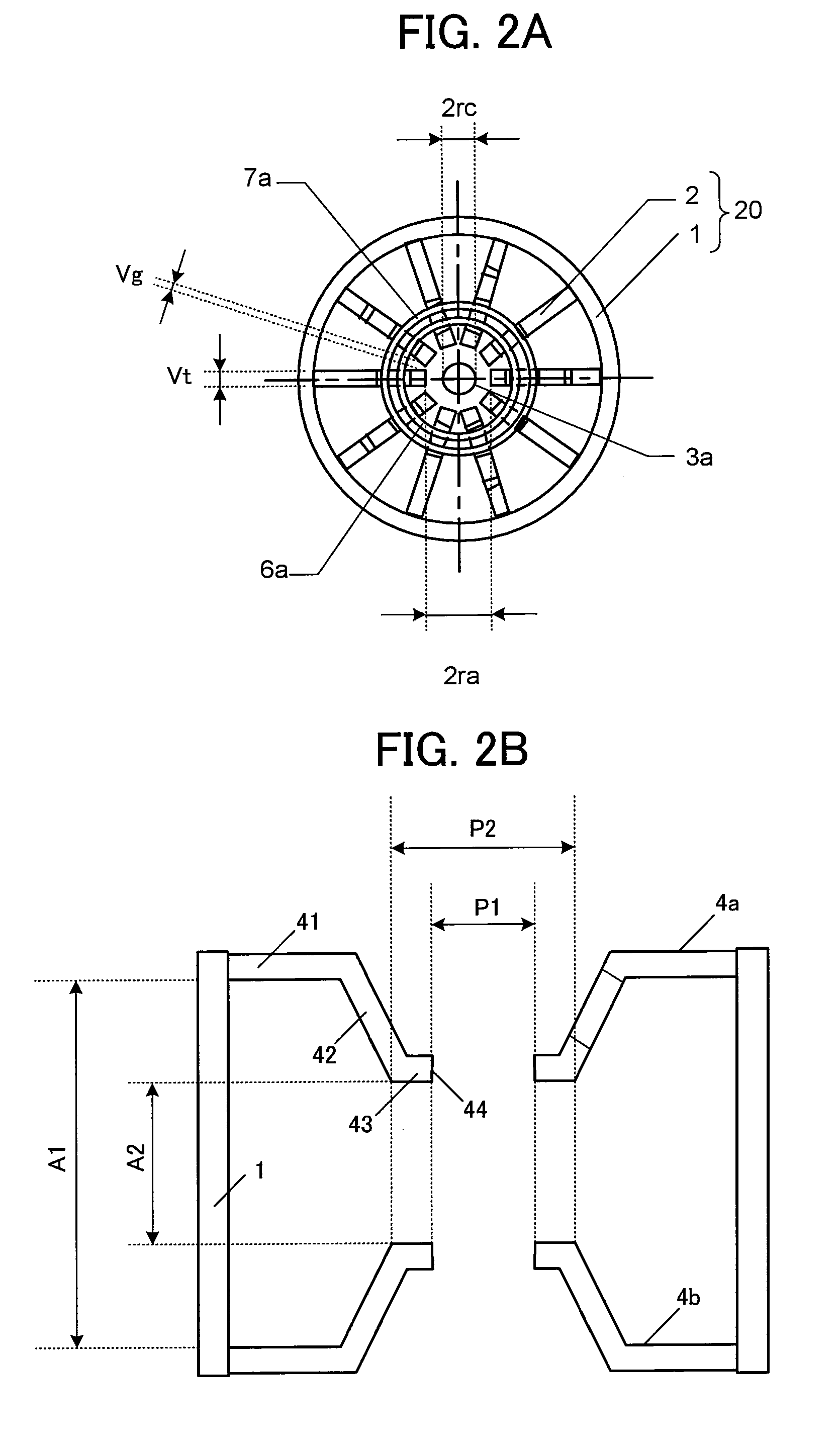
[0027] Referring to the drawings, an embodiment of the present invention will be explained hereinafter. FIG. 1 shows the cross sectional view of the substantial part of the main body of magnetron 100 in accordance with this embodiment. FIG. 2A shows a schematic top view in which the essential portion of the anode part 20 and the cathode part 3 of the magnetron 100 is extracted, and FIG. 2B shows a magnified view of the pole pieces 4a and 4b.

[0028] As shown in FIGS. 1, 2A and 2B, the oscillation body portion of the magnetron 100 is provided with an anode part 20 formed by an anode cylinder 1 and a plurality of vanes 2 arranged radially at an equal interval toward the tube axis k from the inner wall of the anode cylinder 1, and a cathode part 3 having a coil filament 3a arranged along the tube axis k inside the anode cylinder 1. Both ends of the filament 3a are provided with a pair of end hats 3b and 3c.

[0029] The outer end of the vane 2 is secured to the inner wall of the anode cyl...


PUM


Abstract

At an oscillation frequency of 2450 MHz band, number of the vanes constituting the anode part of the magnetron being, the diameter 2ra of the circle inscribing tip portions of the vanes on the cathode side being 8.0 to 8.8 mm, the diameter 2rc of the outer periphery of the filament constituting the cathode part being 3.5 to 3.9 mm, the height A3 of the vane in the direction of the tube axis is 7.0 to 8.0 mm, the mutual distance A1 between the bases of the pair of funnel-shaped pole pieces fixed to both sides of the anode part being 21.5 to 23.5 mm, the mutual distance A2 between the bottom portions of the pair of pole pieces being 10.2 to 11.2 mm, the inner diameter P1 of the through-hole of the pole piece being 8.3 to 8.5 mm, and the outer diameter P2 of the bottom portion being 11.0 to 16.0 mm are set up.

Description

CROSS-REFERENCE TO RELATED APPLICATIONS [0001] This application is based upon and claims the benefit of priority Japanese Patent Application No. 2006-168505, filed on Jun. 19, 2006, the entire contents of which are incorporated herein by reference. BACKGROUND OF THE INVENTION [0002] 1. Field of the Invention [0003] The present invention relates to a magnetron used for a microwave heating apparatus. [0004] 2. Description of the Related Art [0005] The magnetron is an electron tube generating microwaves, which is used in a microwave heating apparatus such as a microwave oven. The oscillating body portion of the magnetron is provided with an anode part comprising an anode cylinder and a plurality of vanes radially arranged toward the tube axis from the inner wall of the anode cylinder, and a cathode part having a coil filament arranged along the tube axis of the anode cylinder. The both ends, that is an output part side and an input part side, of the anode cylinder are provided with a p...

Claims


Application Information

Patent Timeline
Patent Type & Authority Applications(United States)
IPC IPC(8): H03C3/32
CPCH01J23/10H01J25/587H01J23/20H01J23/12
Inventor KATO, NAOYAHIGASHI, MASATOSHIKAWAGUCHI, TOSHIOHAYASHI, SHINJI
Owner TOSHIBA HOKUTO ELECTRONICS CORP
Why Eureka
Try Eureka