
Vehicle Lamp Inspection Equipment and Inspection Method

a technology for inspection equipment and lamps, which is applied in the direction of optical radiation measurement, structural/machine measurement, instruments, etc., can solve the problems of long inspection time, process risk of malfunction or inspection failure, and difficulty in determining which lamp is turned

Inactive Publication Date: 2007-12-27
HONDA MOTOR CO LTD
View PDF7 Cites 19 Cited by
  • Summary
  • Abstract
  • Description
  • Claims
  • Application Information

AI Technical Summary

Benefits of technology

[0019] It is an object of the present invention to provide an automatic vehicle inspecting apparatus for automating a process of inspecting a vehicle lamp for its turned-on state and blinking state to prevent a human-induced inspection error from occurring and also to make a quick inspection possible.
[0020] Another object of the present invention is to provide a vehicle lamp inspecting method which is capable of inspecting a lamp simply and quickly without the need for a complex and expensive vehicle positioning mechanism.
[0021] Still another object of the present invention is to provide a vehicle lamp inspecting method which is capable of distinguishing and inspecting lamps of a lamp unit with a simple apparatus and procedure.

Problems solved by technology

Therefore, when these lamps are inspected for their energization, it is difficult to determine which one of the lamps is turned on.
Such a process has a risk of malfunction or an inspection failure.
Also, since the switches are operated manually, a long period of inspection time tends to be required depending on different skill levels of workers.
If the entire screen of such image data is processed, then a long period of image processing time is required.
Such a positioning mechanism needs large actuators, highly accurate sensors, and complex mechanisms, causes concerns over a high cost for its implementation, and needs an extra time for positioning the vehicle at the time it is inspected, resulting in a tendency to lower the inspection efficiency.
If there are a plurality of types of vehicles to be inspected, then a complex process is required to change the operation of the positioning mechanism for each of the vehicle types.
According to Japanese Laid-Open Patent Publication No. 8-15093, the cost is high and the scale of equipment is large because mechanisms such as a screen and a camera aperture detecting means are used to inspect the headlamp.
Furthermore, the disclosed method makes it difficult to inspect a small lamp for energization since a light beam with a small amount of light is not projected onto the screen.
If the entire screen of such image data is processed, then the image processing requires a long time.
According to the method of determining a skew of the vehicle in a horizontal direction from the positions of the upper and lateral sides of the headlamp, as disclosed in Japanese Laid-Open Patent Publication No. 6-129945, if a plurality of lamps other than the headlamp are to be inspected, then inspection windows established for the respective lamps tend to be vertically displaced, with the result that a lamp to be inspected may run off the edge of an inspection window.

Method used


Image

  • Vehicle Lamp Inspection Equipment and Inspection Method
  • Vehicle Lamp Inspection Equipment and Inspection Method
  • Vehicle Lamp Inspection Equipment and Inspection Method

Examples


Embodiment Construction

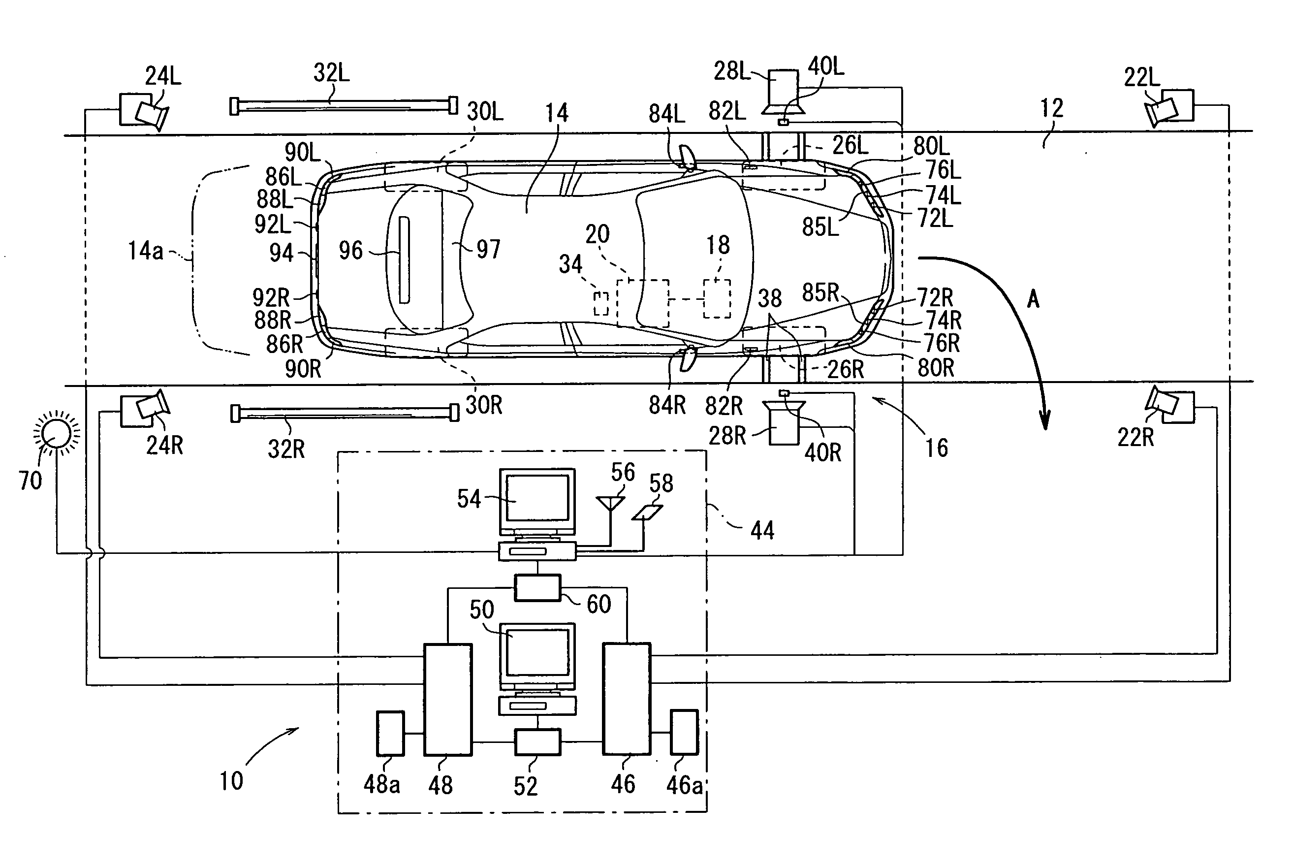
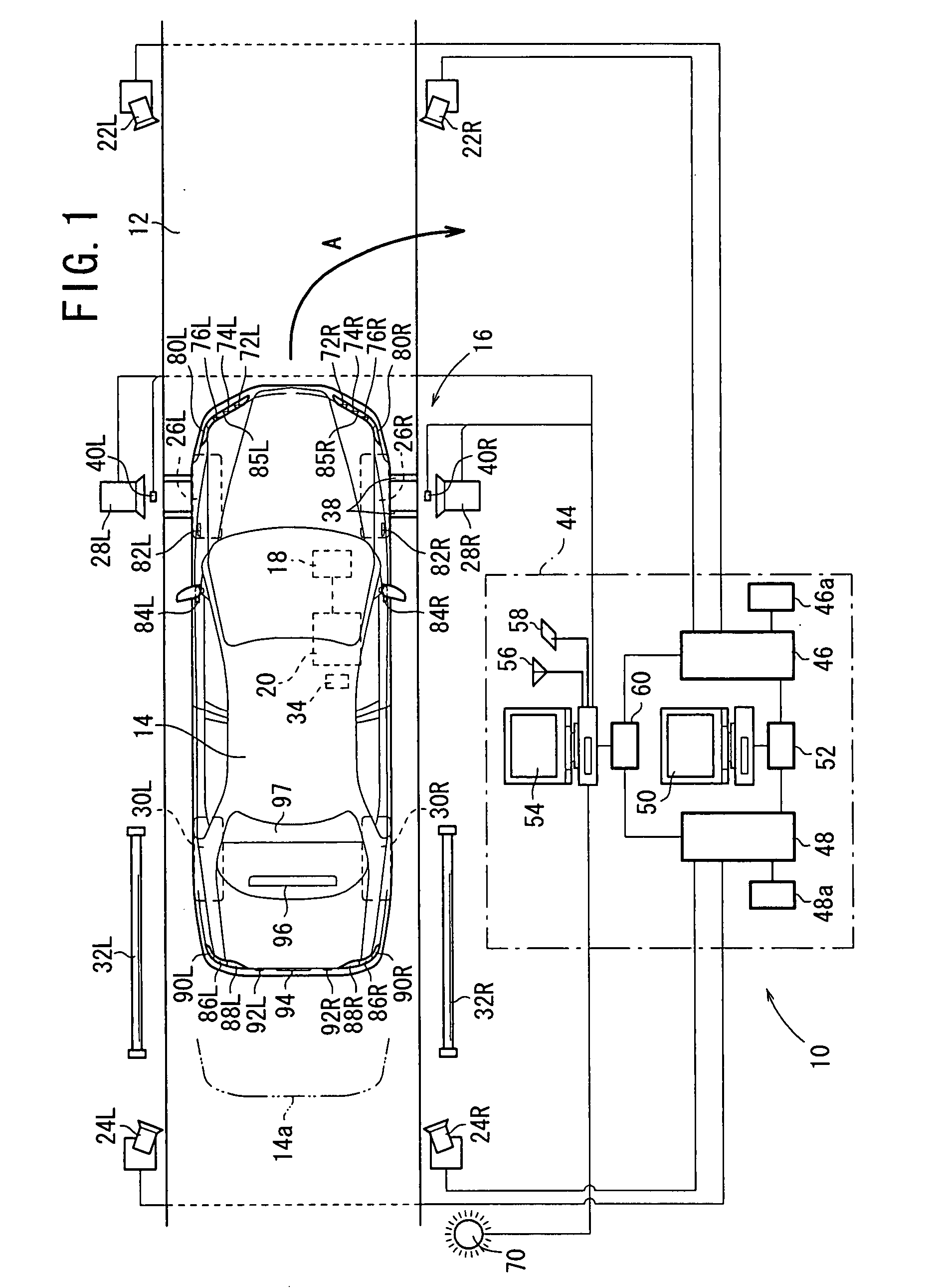
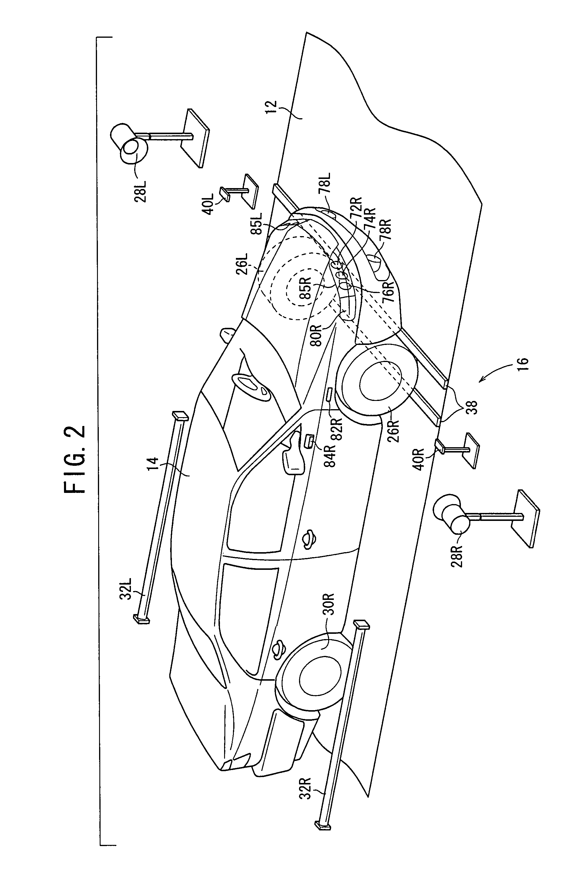
[0062] A vehicle lamp inspecting apparatus according to an embodiment of the present invention will be described below with reference to FIGS. 1 through 15 of the accompanying drawings. In a vehicle lamp inspecting apparatus 10 and a vehicle 14, the mechanisms that are provided one on the left side and one on the other will be distinguished from each other by “L” added to the reference numeral assigned to the left mechanism and “R” added to the reference numeral assigned to the right mechanism.

[0063] As shown in FIG. 1, the vehicle lamp inspecting apparatus 10 according to the embodiment is an apparatus for inspecting various lamps of a vehicle 14 that is driven by the inspector to enter a track 12. The vehicle lamp inspecting apparatus 10 has a vehicle position recognizing unit 16 for detecting when the vehicle 14 reaches and stops at a prescribed inspection position, a terminal unit 20 connected to an ECU (Electronic Control Unit) 18 mounted on the vehicle 14, cameras (image capt...


PUM


Abstract

A vehicle lamp inspection equipment comprises a vehicle position recognizing section for detecting arrival of a vehicle at an inspection position, a terminal to be connected with an ECU mounted on the vehicle, cameras for imaging the lamp of the vehicle which has arrived at the inspection position from the right and left front, cameras for imaging from the right and left rear, spot lights for illuminating the right and left wheels and long fluorescent lights for illuminating the right and left rear wheels. When the vehicle has arrived at the inspection position, a main processing section turns on or flashes the lamp through the terminal and the ECU and acquires image data from the cameras, thereby checking the lamp.

Description

TECHNICAL FIELD [0001] The present invention relates to an apparatus (equipment) for and a method of inspecting various vehicle lamps for their turned-on state and blinking state on an inspection line after vehicles have been assembled. BACKGROUND ART [0002] Processes for manufacturing and assembling vehicles include various inspecting processes performed on vehicles after they have been assembled. The inspecting processes include a confirmative inspection for inspecting whether or not a lamp on a vehicle is properly turned on or blinked to confirm a failure such as a wire disconnection or a bulb burnout. [0003] The lamp inspection is carried out as follows: The inspector actually gets into the vehicle and sits on the driver seat, and directly operates a switch to turn or blink the lamp. The inspector confirms the turning-on or blinking of the lamp by looking at images captured by cameras and displayed on a monitor or mirrors around the vehicle. [0004] As a technology for automating...

Claims


Application Information

Patent Timeline
IPC IPC(8): G01J1/00
CPCG01M11/067G01M11/064G01M11/06
Inventor SEKINE, KEITAFUKAMACHI, KAZUYUKIFUNAHARA, KAZUAKIKAWAGUCHI, RYOHEI
Owner HONDA MOTOR CO LTD
Learn More