Synchronous voltage modulation circuit for resonant power converter

a resonant power converter and synchronous voltage technology, applied in the field of synchronous output voltage modulation circuits of resonant power converters, can solve the problems of resonant controllers b>60/b> only performing closed loop voltage stabilization, output voltages may not be very accurate, etc., to achieve stable power output to load, increase or decrease the conductance period of each electronic switch

Inactive Publication Date: 2007-12-27
ACBEL POLYTECH INC
View PDF6 Cites 28 Cited by
  • Summary
  • Abstract
  • Description
  • Claims
  • Application Information

AI Technical Summary

Benefits of technology

[0013]Each of the power converter modulators first obtains the power converter state (power usage of the load) of the corresponding power output. With the resonance frequency of the resonance current waveform of the transformer obtained by the resonance current extracting unit, the conduction periods of the electronic switches on the secondary sides of the tr...

Problems solved by technology

However, early serial resonant converters only provide one set of power output.
For some applications that require multiple outputs of a power converter, it is more difficult for the above-mentioned resonant converter circuits to provide each output set with accurate and stable power at the same time.
Anyway, these output voltages may not be very accurate.
However, the resonant controller 60 ca...

Method used


Image

  • Synchronous voltage modulation circuit for resonant power converter
  • Synchronous voltage modulation circuit for resonant power converter
  • Synchronous voltage modulation circuit for resonant power converter

Examples


first embodiment

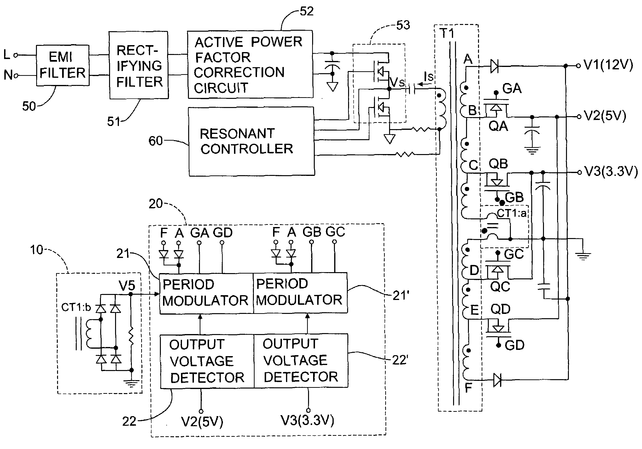
[0023]With reference to FIG. 1 and FIG. 4, FIG. 1 shows the synchronous voltage modulation circuit for a resonant power converter in accordance with the present invention and FIG. 4 shows the detail of the circuit. In this embodiment, it is used in a serial resonant power converter that includes a transformer T1, several electronic switches QA˜QD, a resonant controller 60, a half-bridge switch 53, and an active power factor correction (PFC) circuit 52. The disclosed synchronous voltage modulation circuit has a resonant current extracting unit 10, and at least one duty cycle modulation circuit 20.

[0024]The resonant current extracting unit 10 extracts the resonant current on the transformer T1 of the resonant power converter. In this embodiment, the resonant current extracting unit 10 can be a current sensing element similar to a current transformer (CT) or a resistor, connected to a secondary side of the transformer T1 to extract its secondary side resonant current. Moreover, the res...

second embodiment

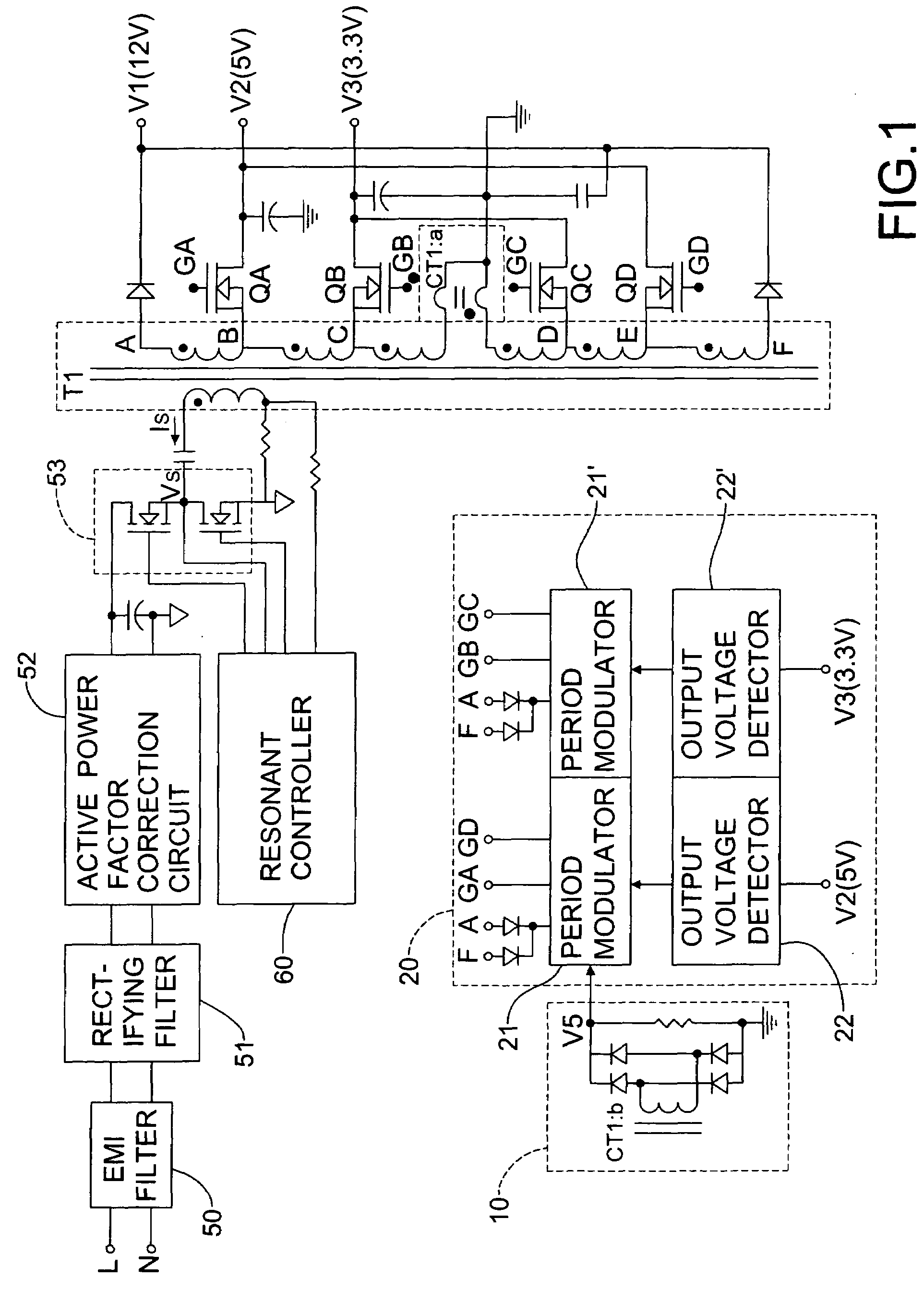
[0032]With reference to FIGS. 2 and 5, in the invention, the synchronous voltage modulation circuit has a resonant current extracting unit 10 and at least one duty cycle modulation circuit 20a as well. However, the duty cycle modulation circuit 20a only includes a period modulator 21, which is a comparator LM339 whose both input terminals are connected to the output terminal of the resonant current extracting unit 10 and a fixed reference voltage Vref, respectively. Since the resonant current extracting current 10 extracts the secondary side resonant current, the resonant current varies with the power usage of the output load. It is directly compared with the reference voltage Vref by the comparator LM339, followed by outputting a control signal that varies with the resonant current. The control signal is output to the driver 30 of the secondary side electronic switches QA˜QD to modulate their conduction period or duty cycle.

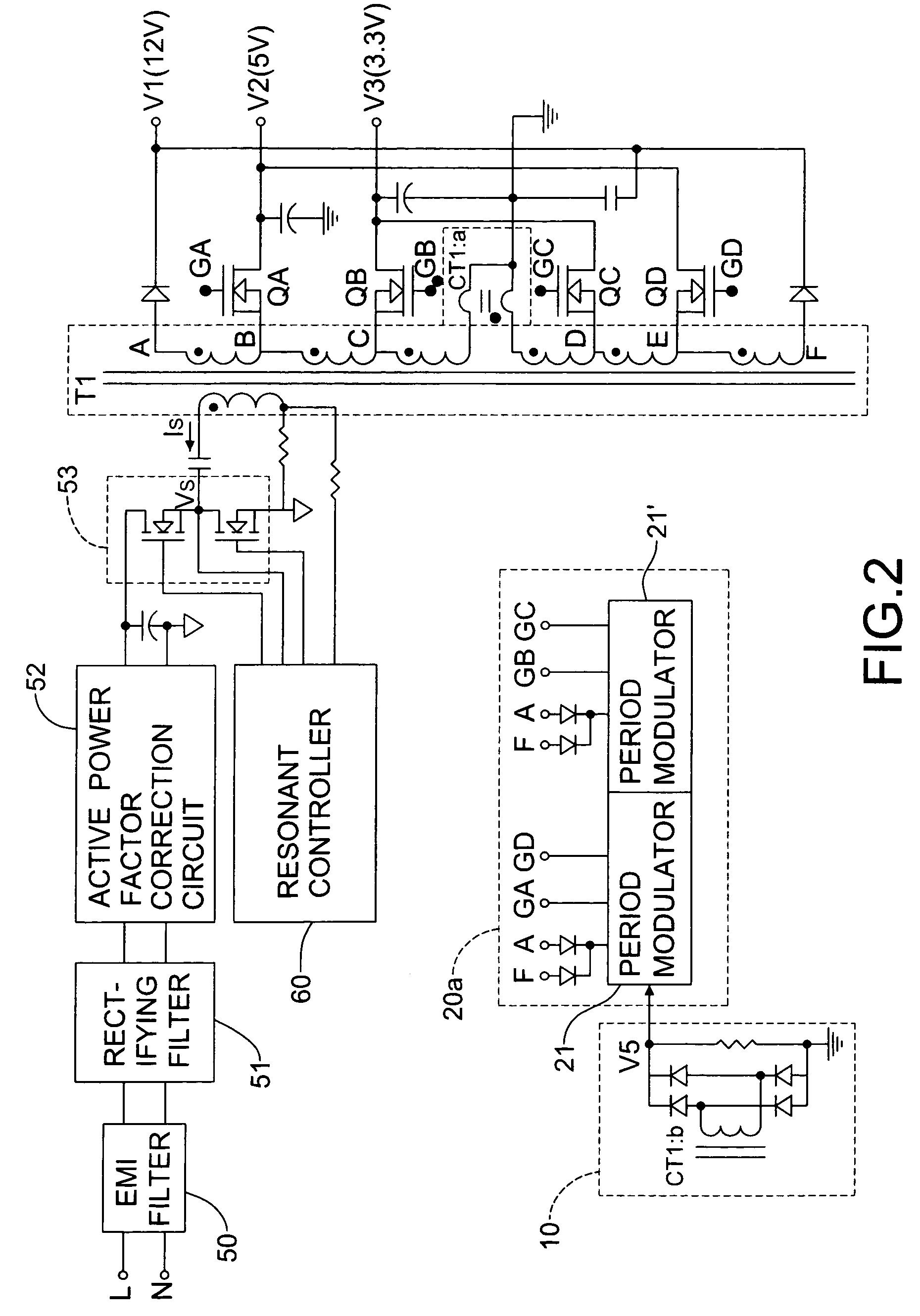
[0033]As shown in FIG. 3, the third embodiment of the disc...


PUM


Abstract

A synchronous voltage modulation circuit for resonance power converter has a resonance current extracting unit and at least one duty cycle modulation circuit. The resonance current extracting unit extracts the resonance current of the transformer for each duty cycle modulation circuit. The duty cycle modulation circuit controls the conduction period of the electronic switch on the secondary side of the transformer according to the power usage of the load connected to the power output and the resonance frequency of the resonance current on the transformer detected by the resonance current extracting unit. The conduction period increases or decreases symmetrically with respect to the central axis. The power converter output of the resonance power converter converter forms a closed loop control, thereby providing stable power to its load.

Description

BACKGROUND OF THE INVENTION[0001]1. Field of the Invention[0002]The invention relates to a circuit of a power converter and, in particular, to a synchronous output voltage modulation circuit for a resonant power converter that accurately controls the output voltage of the resonant power converter and provides power according to the power usage on the load connected to it.[0003]2. Description of Related Art[0004]Serial or parallel resonant power converters are mostly used on power converter to provide stable and high power to their output loads. However, early serial resonant converters only provide one set of power output. They often have a resonant controller like IC L6598 produced by ST Corporation on the primary side of the transformer to drive the power switches and control the electrical energy provided to the secondary side of the transformer. The input terminal of the resonant controller also connects to one output terminal of the power converter to form a closed loop control...

Claims


Application Information

Patent Timeline
IPC IPC(8): H02M3/335
CPCH02M3/33561Y02B70/1433H02M3/337Y02B70/10H02M3/33571H02M3/01
Inventor CHANG, SHUN-TE
Owner ACBEL POLYTECH INC
Why Eureka
Try Eureka