Synchronized wireless mesh network

Inactive Publication Date: 2007-12-27
FOLUSHA FORTE
View PDF49 Cites 46 Cited by
  • Summary
  • Abstract
  • Description
  • Claims
  • Application Information

AI Technical Summary

Benefits of technology

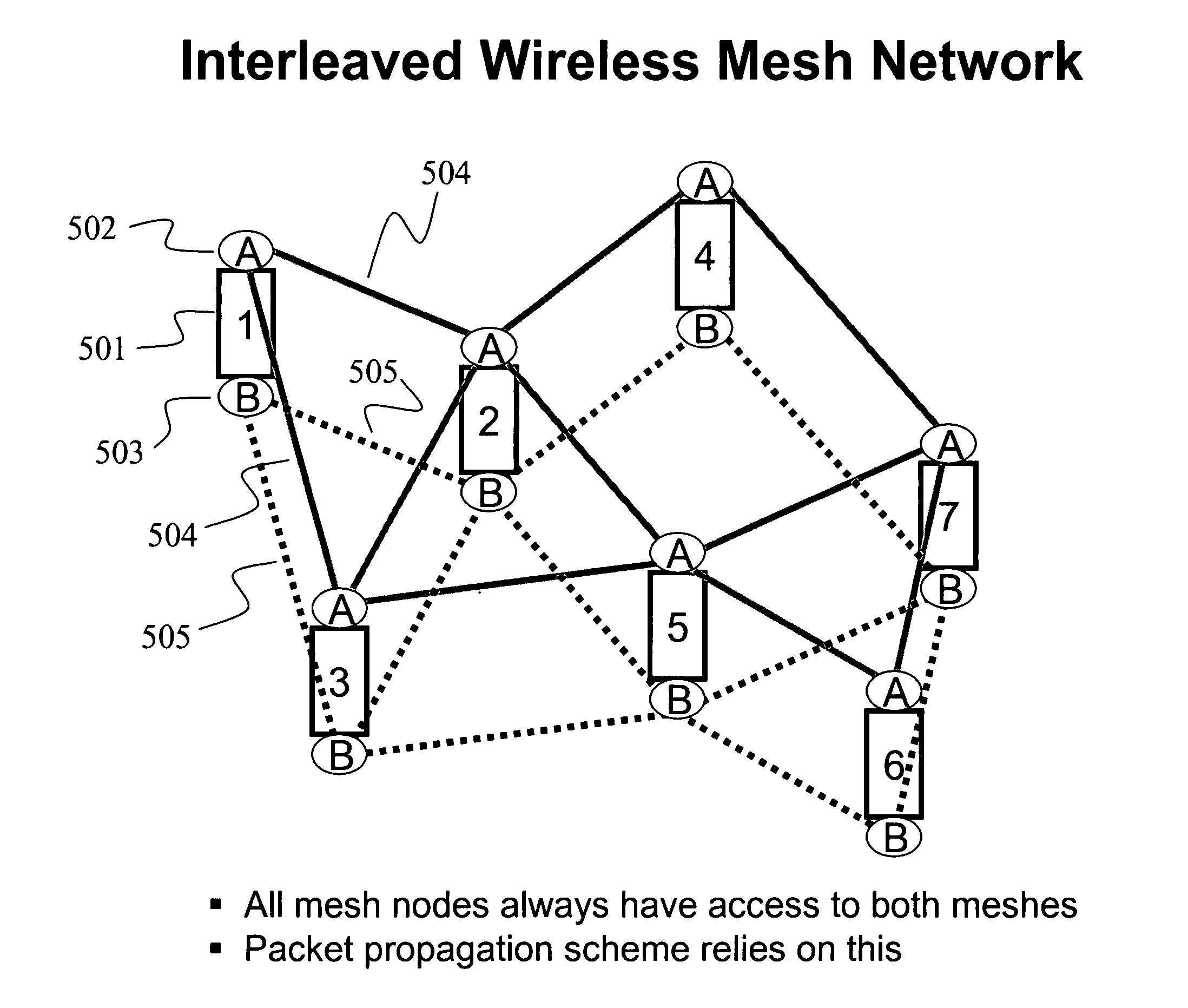
[0019]An interleaved mesh is described that uses at least two relay radios on each node to create two or more simultaneous mesh networks, each on separate channels. A transmitted stream of packets will then utilize any or all of these multiple simultaneous meshes as they propagate through the overall mesh network. For any particular hop, a packet may use any of the available meshes to propagate to the next node. From hop to hop, a particular packet may change which mesh it travels on to reach the next node. Here, two sequential packets in a particular packet stream may travel on the same m

Problems solved by technology

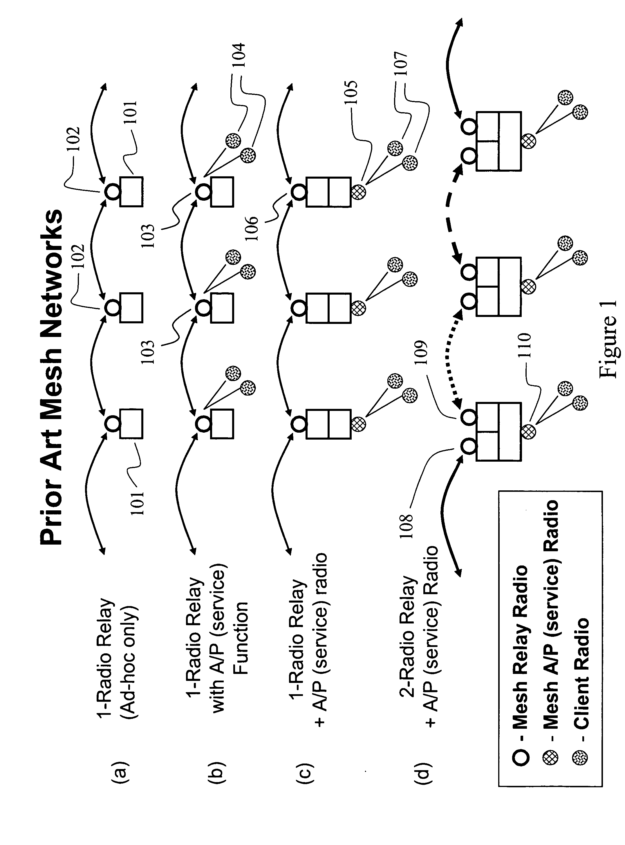
This causes a significant bandwidth limitation since a single radio cannot send and receive at the same time.
The architecture of FIG. 1(b) suffers from performance limitations since the single radio must not only relay packets, but also service numerous client radios 104 at each node.
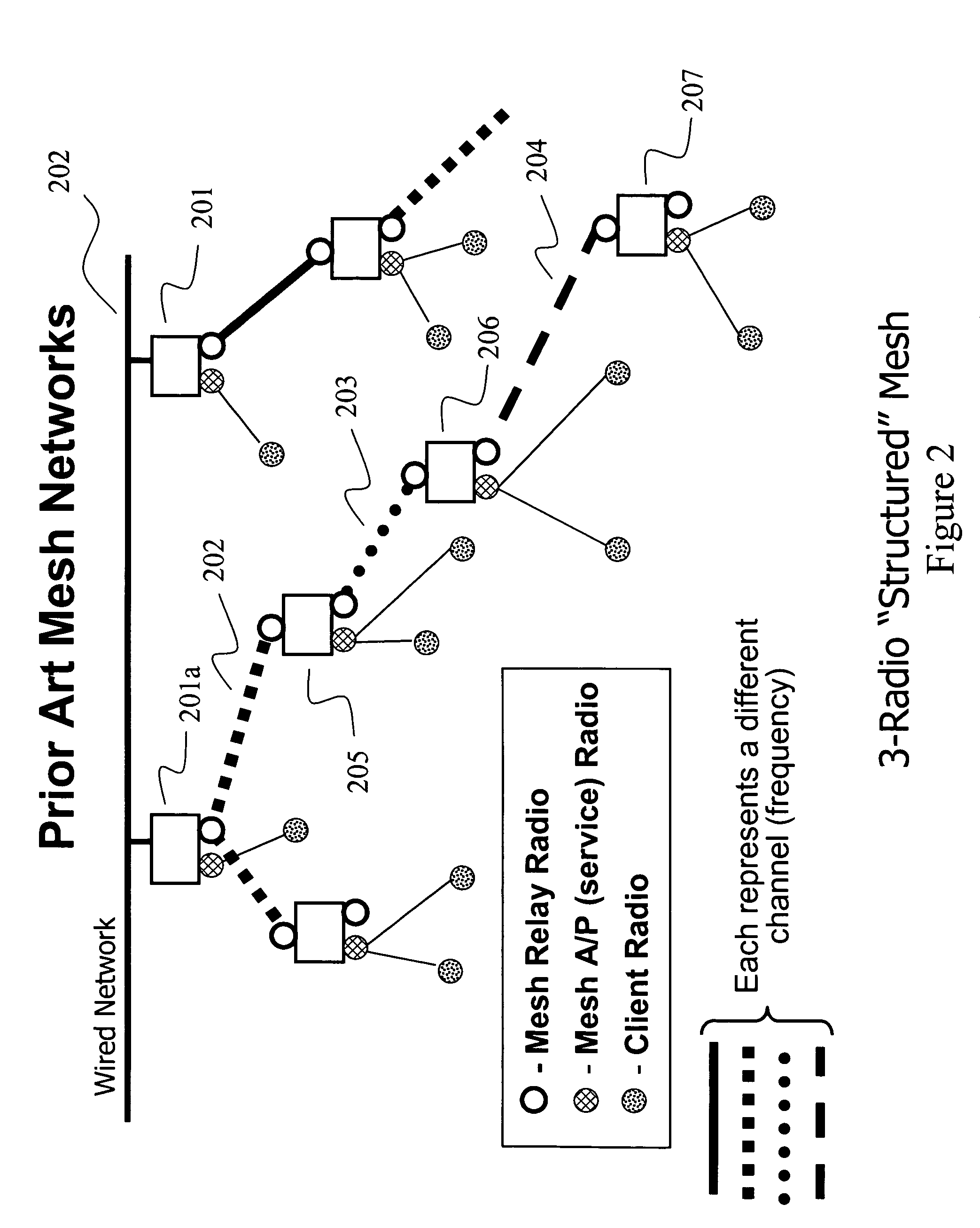
In this type of mesh network, the mesh control software on each node has a significant challenge in assigning the various available channels throughout the mesh such that interference effects are minimized, and the mesh functions properly.
Either way, having a mesh network where channels change from hop to hop is complicated and difficult to deal with.
In the case of a public safety mesh with mobile nodes (for vehicles and individual First Responders on foot), a further problem arises with this form of mesh.
For instance, if a group of first responders each carrying a mesh node become isolated from the backhaul connection to the server (Command and Control), the tree-like structure of FIG. 2 may become compromised since there is no longer a defined root for the tree.
e). Also, when connections between nodes must change because of a node failure, temporary disturbances to the mesh (moving obstacles or rada

Method used


Image

  • Synchronized wireless mesh network
  • Synchronized wireless mesh network
  • Synchronized wireless mesh network

Examples


Embodiment Construction

[0061]The invention is illustrated by way of example and not by way of limitation in the figures of the accompanying drawings in which like references indicate similar elements. References to embodiments in this disclosure are not necessarily to the same embodiment, and such references mean at least one. While specific implementations are discussed, it is understood that this is done for illustrative purposes only. A person skilled in the relevant art will recognize that other components and configurations may be used without departing from the scope and spirit of the invention.

[0062]In the following description, numerous specific details are set forth to provide a thorough description of the invention. However, it will be apparent to those skilled in the art that the invention may be practiced without these specific details. In other instances, well-known features have not been described in detail so as not to obscure the invention.

[0063]One of the key components of the present inv...


PUM


Abstract

A synchronized wireless mesh network is described where mesh nodes have one or more relay radios and multiple directional antennas aimed in horizontally orthogonal directions. A rectangular grid of such mesh nodes can include at least 4 nodes arranged in a rectangular formation such that diagonally aligned nodes are incapable of communicating directly to each other. Adjacent nodes, on the other hand, can be controlled to transmit and receive to each other in an alternating sequence. Thus, diagonally aligned nodes can be controlled to transmit and receive in unison. Such a network can enable for greater speed and simultaneity of packet propagation and provide for less interference amongst adjacent nodes. Other embodiments are also described where radio transmission and reception at a particular node having multiple radios are synchronized to eliminate co-channel, adjacent channel and cross-channel interference.

Description

CLAIM OF PRIORITY[0001]This application claims the benefit and priority of U.S. Provisional Application Ser. No. 60 / 756,794, filed on Jan. 5, 2006, and entitled “DIRECTIONAL AND INTERLEAVED WIRELESS MESH NETWORKS,” commonly assigned with the present application and incorporated herein by reference.CROSS REFERENCES TO RELATED APPLICATIONS[0002]This application is related to and cross references the following U.S. patent applications, which are incorporated herein by reference:[0003]U.S. patent application Ser. No. XX / XXX,XXX entitled “INTERLEAVED WIRELESS MESH NETWORK,” by Robert Osann, Jr., filed on XXXX, 2006, Attorney Docket No. OSAN-01004US0.[0004]U.S. patent application Ser. No. XX / XXX,XXX entitled “INTERLEAVED AND DIRECTIONAL WIRELESS MESH NETWORK,” by Robert Osann, Jr., filed on XXXX, 2006, Attorney Docket No. OSAN-01003US0.[0005]U.S. patent application Ser. No. XX / XXX,XXX entitled “COMBINED DIRECTIONAL AND MOBILE INTERLEAVED WIRELESS MESH NETWORK,” by Robert Osann, Jr., filed...

Claims


Application Information

Patent Timeline
IPC IPC(8): H04Q7/00H04W28/04H04W40/06H04W56/00H04W84/18H04W88/04
CPCH04W28/04H04W40/06H04W88/04H04W84/18H04W56/00
Inventor OSANN, ROBERT
Owner FOLUSHA FORTE
Why Eureka
Try Eureka