Code generator and decoder for communications systems operating using hybrid codes to allow for multiple efficient users of the communications systems

a technology of communication system and code generator, applied in the direction of code conversion, code conversion, instruments, etc., can solve the problems of data loss, data transmission becomes more difficult, erasure, sent or stored by the sender is different, etc., and achieve the effect of more error protection

Inactive Publication Date: 2007-12-27
QUALCOMM INC
View PDF13 Cites 100 Cited by
  • Summary
  • Abstract
  • Description
  • Claims
  • Application Information

AI Technical Summary

Benefits of technology

[0024] According to one embodiment of the invention, a method of encoding data for transmissions from a source to a destination over a communications channel is provided. The method operates on an ordered set of source symbols and may generate zero or more redundant symbols from the source symbols, wherein data is encoded in a first step according to a first FEC code and in a second step, data is encoded according to a second FEC code, more complex than the first FEC code. The first FEC code might be a simple erasure code and the second a more complex erasure code. The first FEC code and / or the second FEC code might comprise coding known in the art. These steps result in two groups of encoded data in such a way that a low-complexity receiver may make use of one of the groups of encoded data while higher complexity receivers may make use of both groups of encoded data, providing more error protection than either FEC code alone.

Problems solved by technology

Lost data (erasures) are often easier to deal with than corrupted data (errors) because the recipient cannot always recognize when the transmitted data has been corrupted.
In realizable channels, there is often a nonzero chance that the data sent or stored by the sender is different when it is received or read by the recipient and those differences might be due to errors introduced in the channel.
Data transmission becomes more difficult when the channel is in an adverse environment, or the transmitter and / or receiver has limited capability.
In certain applications, uninterrupted error-free communication is required over long periods of time.
In these cases, the problem of data transmission is difficult even in conditions of relatively low levels of errors.
Another scenario in which data communication is difficult is where a single transmission is directed to multiple receivers that may experience widely different data loss conditions.
Often, however, a reverse channel is not available or feasible, or is available only with limited capacity.
For example, in cases in which the transmitter is transmitting to a large number of receivers, the transmitter might not be able to maintain reverse channels from all the receivers.
As a result, communication protocols often need to be designed without a reverse channel or with a limited capacity reverse channel and, as such, the transmitter may have to deal with widely varying channel conditions without prior knowledge of those channel conditions.
Both file transmission and stream transmission can instead be not entirely reliable, but somewhat reliable, in the sense that some parts of the file or stream are not recoverable or, for streaming, some parts of the stream might be recoverable but not in a timely fashion.
Packet loss often occurs because sporadic congestion causes the buffering mechanism in a router to reach its capacity, forcing it to drop incoming packets.
However, a known disadvantage of Reed-Solomon codes is their relatively high computational complexity.
As a general rule, erasure codes that are capable of correcting large amounts of lost data have a greater cost in terms of computational complexity, device hardware and software complexity, and / or memory requirements than those codes which are designed only for very limited levels of errors.
The complexity of encoding and decoding such a code is very low.
A disadvantage of known techniques is that if losses for some receivers are such that a more powerful erasure correction code must be employed, then all receivers need to provide support for this powerful code, implying costs in terms of complexity, memory, etc. for all receivers.
The “flag day” problem is a well-known problem that is difficult to solve in practice.
The flag day problem occurs in large communication systems involving many devices (senders and receivers) when it becomes necessary to upgrade all deployed devices (e.g., receivers) simultaneously in order to deploy an upgraded service.
The flag day problem has delayed or prevented the implementation of a number of desirable upgrades to systems in cases in which the upgrade is characterized by the precondition that all devices need to be updated before the system will work correctly, i.e., the system will not even perform at pre-upgrade levels if some devices have been upgraded and other devices have not.
This can be a large problem if a full upgrade would take a prolonged period of time.
In such cases, a seamless upgrade path is highly desirable but is often difficult to accomplish.

Method used


Image

  • Code generator and decoder for communications systems operating using hybrid codes to allow for multiple efficient users of the communications systems
  • Code generator and decoder for communications systems operating using hybrid codes to allow for multiple efficient users of the communications systems
  • Code generator and decoder for communications systems operating using hybrid codes to allow for multiple efficient users of the communications systems

Examples


Embodiment Construction

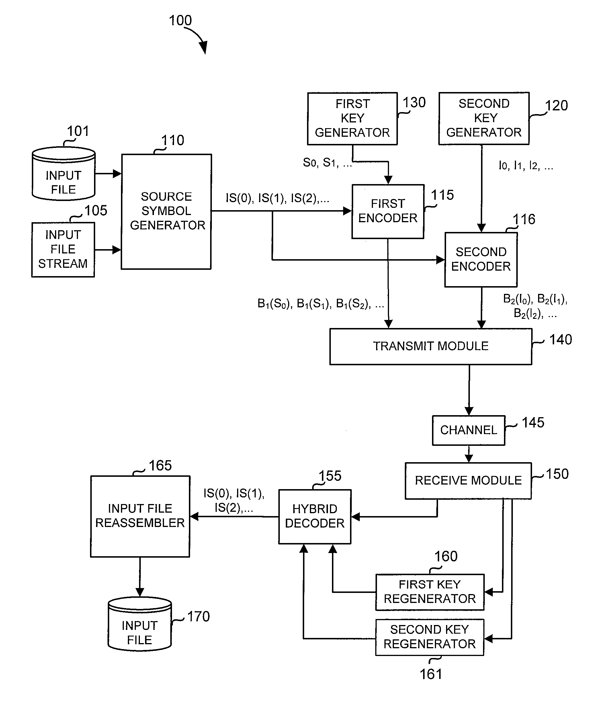
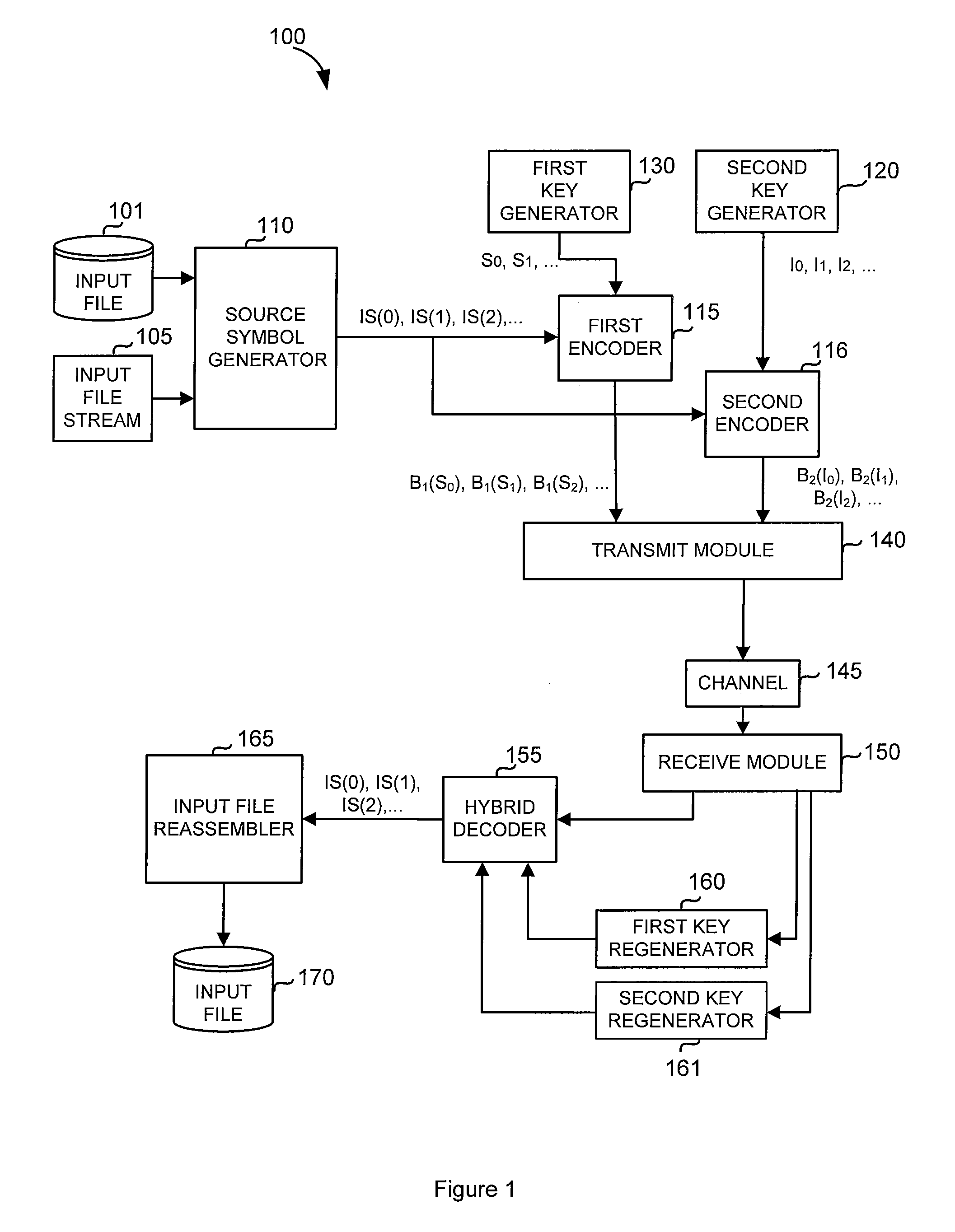
[0034] It is to be understood that the various functional blocks described herein may be implemented by a combination of hardware and / or software, and that in specific implementations some or all of the functionality of some of the blocks may be combined. Similarly, it is also to be understood that the various methods described herein may be implemented by a combination of hardware and / or software. Thus, where a computational step is performed, which might be described as “we then do step X”, it should be understood that such descriptions include electronic hardware and / or software, or the like, performing those steps, typically as part of a communications process and not involving human or manual interaction.

[0035] In embodiments described herein, data to be encoded is segmented into “source blocks,” each block comprising a number of packets of data, known as “source packets,” with the number of source packets in a block possibly varying between blocks. For each source block, a nu...


PUM


Abstract

A method of encoding data for transmissions from a source to a destination over a communications channel is provided. The method operates on an ordered set of source symbols and may generate zero or more redundant symbols from the source symbols, wherein data is encoded in a first step according to a simple FEC code and in a second step, data is encoded according to a second FEC code, more complex than the first FEC code. The first FEC code and/or the second FEC code might comprise coding known in the art. These steps result in two groups of encoded data in such a way that a low-complexity receiver may make use of one of the groups of encoded data while higher complexity receivers may make use of both groups of encoded data.

Description

CROSS-REFERENCES [0001] This application claims priority from and is a non-provisional of U.S. Provisional Patent Application No. 60 / 799,536 filed May 10, 2006. [0002] The following references are include here and are incorporated by reference for all purposes: [0003] U.S. Pat. No. 6,307,487 entitled “Information Additive Code Generator and Decoder for Communication Systems” issued to Luby (hereinafter “Luby I”); [0004] U.S. Published Patent Application No. 2005 / 0257106 published Nov. 17, 2005 and entitled “File Download and Streaming System” to Luby, et al. (hereinafter “Luby II”); [0005] U.S. Pat. No. 7,068,729 entitled “Multi-Stage Code Generator and Decoder for Communication Systems” issued to Shokrollahi, et al. (hereinafter “Shokrollahi I”); [0006] U.S. Published Patent Application No. 2006 / 0036930 published Feb. 16, 2006 and entitled “Method and Apparatus for Fast Encoding of Data Symbols According to Half-Weight Codes” to Luby, et al. (hereinafter “Luby III”); and [0007] U.S...

Claims


Application Information

Patent Timeline
Patent Type & Authority Applications(United States)
IPC IPC(8): H03M13/09H03M13/15
CPCH03M13/03H04L1/0064H04L1/0052
Inventor WATSON, MARKLUBY, MICHAEL G.
Owner QUALCOMM INC
Why Eureka
Try Eureka