Method and system for multi-domain route computation

a multi-domain route and computation technology, applied in the field of communication technologies, can solve the problems of difficult to compute end-to-end diverse routes, difficult to manage and maintain route computation, serial process of route computation, etc., to avoid rollback risk, increase the efficiency of route computation, and reduce the volume of communication between pces

Active Publication Date: 2008-01-03
HUAWEI TECH CO LTD
View PDF8 Cites 46 Cited by
  • Summary
  • Abstract
  • Description
  • Claims
  • Application Information

AI Technical Summary

Benefits of technology

[0025] The present invention brings many benefits: route computation processes can run in parallel, which increases the efficiency of route computation; route computation is performed before a route is established by signaling, which avoids the risk of rollback if route establishment fails; the volume of communication between PCEs is largely reduced; end-to-end diverse route computation is easy to implement; route computation for a large network is easy.

Problems solved by technology

When a communication network becomes huge, its management and maintenance will be difficult.
As each node knows only the TE information of the local domain and the reachable information of other domains but does not know the complete TE information of other domains, it becomes an issue how to compute a path that meets all the constraints on end-to-end bandwidth, switching capability, route separation, protection, and user policies in the case of multiple domains.
The defect of this solution is that route computation is a serial process.
In addition, with the DDRP technology, it is hard to compute end-to-end diverse routes (different paths with the same source and destination).
When the network is complex or large, it is difficult to manage the PCEs.
When a service passes through many domains, communication between related PCEs will be too frequent and the volume of information exchanged will be huge.
This will reduce the efficiency and reliability of route computation.

Method used


Image

  • Method and system for multi-domain route computation
  • Method and system for multi-domain route computation
  • Method and system for multi-domain route computation

Examples


first embodiment

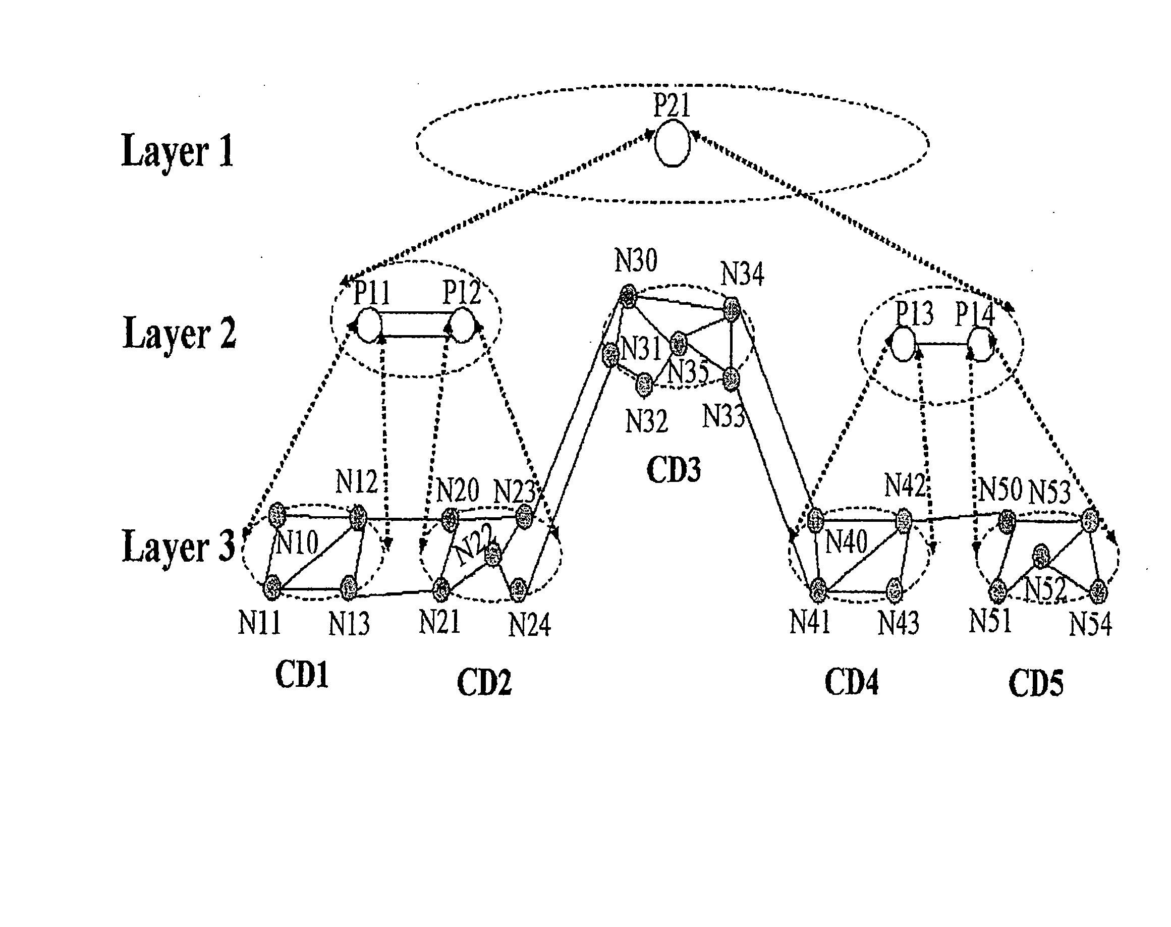
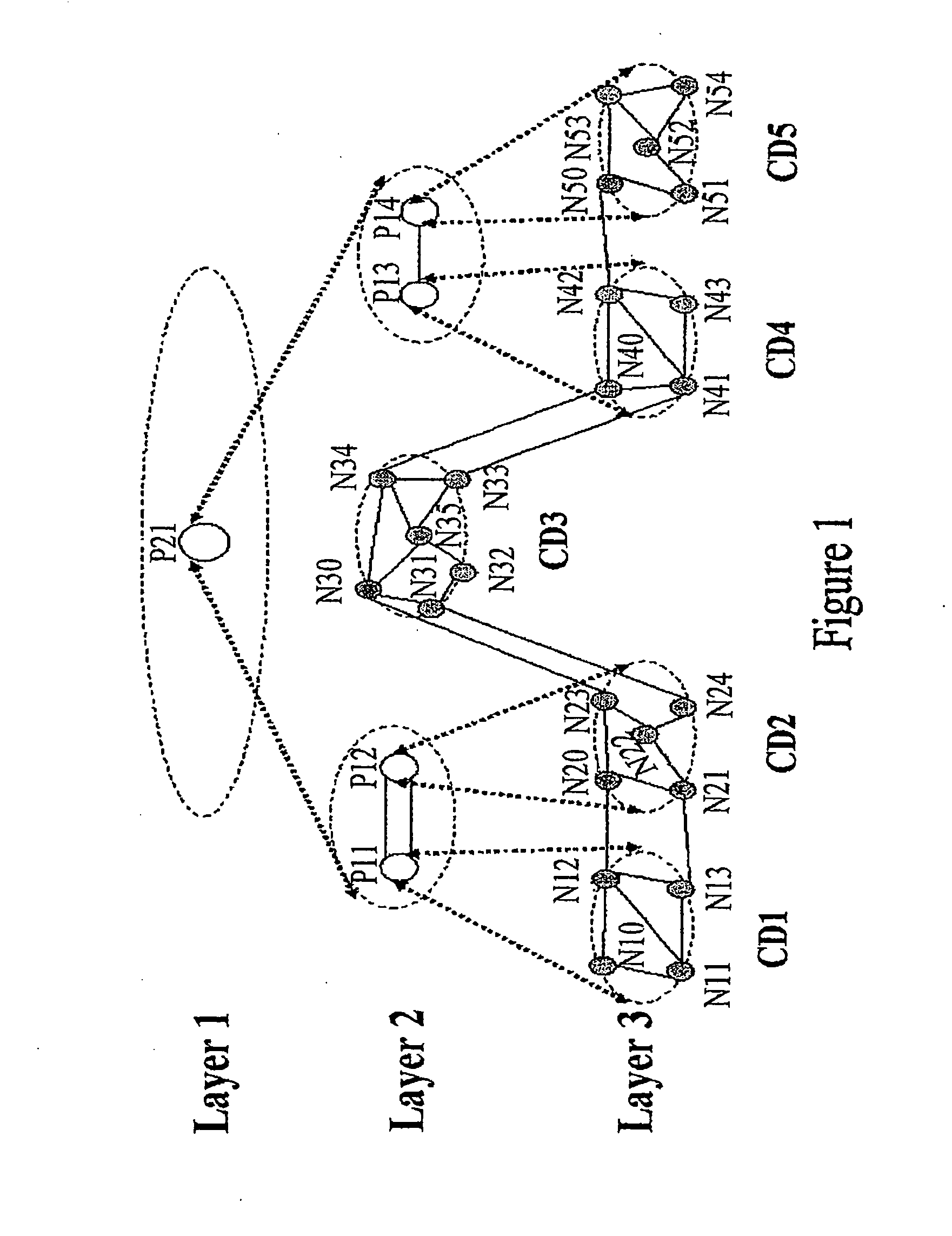
[0041] In the method, when a user sends a command to establish a service connection between N10 and N13, route computation is carried out in the following procedure:

[0042] Step A: Determine a PCE whose computation domain may include both N10 and N13. Because when the source node N10 requests P11 whose computation domain includes N10, to do route computation, P11 may determine that the destination node N13 is also included in its computation domain. Therefore, it can be determined that P11 is the PCE whose commutation domain includes both N10 and N13. This means, P11 is the top layer PCE for this route computation.

[0043] Step B: P11 and its lower layer PCEs complete the route computation together. Because P11 has no immediate lower layer PCE, it does the route computation directly. The computation result is, for instance, N10→N11→N13.

second embodiment

[0044] In the method, when a user sends a command to establish a service connection between N10 and N53, route computation is carried out in the following procedure:

[0045] Step A: Determine a PCE whose computation domain may include both N10 and N53. This step further includes:

[0046] Step A1: The source node N10 sends a request for route computation to P11 whose computation domain includes N10.

[0047] Step A2: P11 finds that N53 is not included in its computation domain, or the computation domain of P11 does not include N10 and N53 at the same time. Then P11 forwards the request for route computation to its immediate upper layer PCE, P21.

[0048] Step A3: P21 finds that N10 is included in the computation domain of P11, one of its immediate lower layer PCEs, and that N53 is included in the computation domain of P14, another of its immediate lower layer PCEs. This means the computation domain of P21 may include both N10 and N53. Therefore, P21 determines that it is the PCE whose compu...
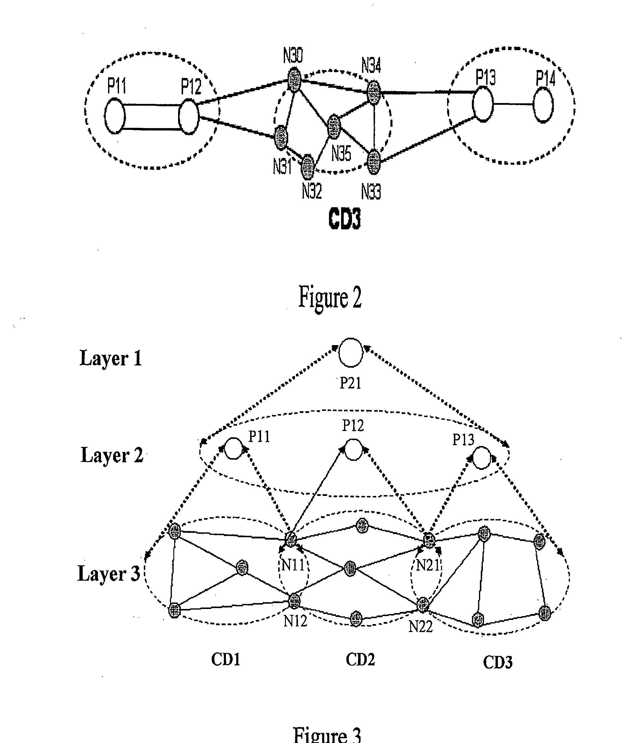
third embodiment

[0058] In the method, when a user sends a command to establish a service connection between N10 and N53, route computation is carried out in the following procedure:

[0059] Step A: Determine a PCE whose computation domain may include both N10 and N53.

[0060] This step Her includes:

[0061] Step A1: Source node N10 sends a request for route computation to P11, whose computation domain includes N10; N10 (or P11) notifies destination node N53 to do route computation and N53 sends a request for route computation to P14, whose computation domain includes N53.

[0062] Step A2: P11 detects N53 is not included in its computation domain, which means the computation domain of P11 does not include N10 and N53 simultaneously. Therefore, P11 forwards the request for route computation to P21, which is its immediate upper layer PCE and sends its computation result N10→N12 to P21 for reference. P14 detects that N10 is not included in its computation domain, which means the computation domain of P14 do...


PUM


Abstract

A method and system for multi-domain route computation. In the invention, Path Computation Elements (PCEs) are placed in different layers and computation domains between upper and lower layer PCEs are mapped so that a computation task is divided into multiple computation tasks layer by layer and that the multi-domain route computation is finally fulfilled. The invention separates route computation from signaling and runs route computation tasks in parallel. Route establishment is done by signaling after route computation. The present invention may realize route computation based on complex Traffic Engineering (TE) constraints and enable end-to-end diverse route computation. The invention places PCEs in layers, allowing good scalability and high computation efficiency. The present invention is applicable to the Automatically Switched Optical Network (ASON) and the Multi-Protocol Label Switched Network Traffic Engineering (MPLS-TE) network.

Description

FIELD OF THE INVENTION [0001] The present invention relates to communication technologies, and in particular to a method and system for multi-domain route computation in a communication network. BACKGROUND OF THE INVENTION [0002] A communication network is a set of geographically distributed nodes and the links between these nodes for data transmission. The communication between two nodes may be realized by way of intermediate nodes. This saves resources of the communication network and improves the resource efficiency. Present communication networks operate in various types, including SDH / SONET networks and IP networks. Different nodes in a communication network communicate with each other by exchanging data frames or packets, which are defined by special protocols like TCP / IP. The protocol herein means a set of rules defining inter-node interaction, similar to TCP / IP. [0003] When a communication network becomes huge, its management and maintenance will be difficult. Usually to fac...

Claims


Application Information

Patent Timeline
Patent Type & Authority Applications(United States)
IPC IPC(8): H04L12/28H04L45/42
CPCH04L45/04
Inventor LI, QIMINGXU, HUIYING
Owner HUAWEI TECH CO LTD
Why Eureka
Try Eureka