Autofocusing still and video images

a technology of autofocus and still images, applied in the direction of exposure control, camera focusing arrangement, printers, etc., can solve the problems of affecting the focus quality of all video images, the calibration between the dual lens rangefinder module and the moveable lens position is not stable within the normal operating environment of digital cameras, and the measured position of the moveable lens in the moveable lens control system is prone to environmental induced changes, so as to improve the resolution and image quality of video images captured by digital capture devices

Active Publication Date: 2008-01-03
OMNIVISION TECH INC
View PDF11 Cites 30 Cited by
  • Summary
  • Abstract
  • Description
  • Claims
  • Application Information

AI Technical Summary

Benefits of technology

[0017]As the resolution and image quality of video images captured by digital capture devices improves, the print quality of the individual video images will become much more important to consumers. By improving the focus quality of all the video images, the overall quality of the video will be improved and the print quality of each of the video images will be improved as well. Consequently, the continuous use of an autofocus system which is capable of making focus adjustments for video images or still images such as a split aperture device will be important.
[0018]All of the split aperture device embodiments of the invention share the following advantages. First, since the taking lens is used for both the autofocus image captures and the video image captures, there are no parallax issues. Second, since the high quality taking lens is used along with the full resolution sensor to capture the autofocus images, the possibility exists to do autofocus on very high resolution images or high resolution portions of images such as in multi-spot autofocus. Third, the split aperture device can also be used for autofocus of multiple images in a burst mode or during capture of single still images. Fourth, all the split aperture device embodiments operate as a shutter for image capture devices.

Problems solved by technology

Although this approach does deliver an accurate focus condition, it is slow due to the many autofocus images that must be captured and analyzed.
As a result, during video capture with pan movements of the camera where the scene changes continuously, large portions of the video segment are actually out of focus.
Second, the moveable lens movement control system must be fast enough to reposition the moveable lens within 1 / 30 sec.
The problem with the dual lens rangefinder modules is that the calibration between the dual lens rangefinder module and the moveable lens position is not stable within the normal operating environment for digital cameras.
In addition, the measured position of the moveable lens in the moveable lens control system is prone to environmentally induced changes as well.
Keiichi does not use a split color filter system for autofocus during video and in addition, the split color filter used by Keiichi is fixed in the optical path so that substantial light losses are incurred from the split color filter in the optical path during capture of the video images.
In general, the addition of a split color filter to the optical path introduces light losses to the optical system which tend to slow down the autofocus system and make autofocusing under low light conditions difficult.
However, Kurahashi, Horikawa, and Wolbarsht do not use a split aperture device for fast autofocus of stills or for autofocus during video capture.

Method used


Image

  • Autofocusing still and video images
  • Autofocusing still and video images
  • Autofocusing still and video images

Examples


example 1

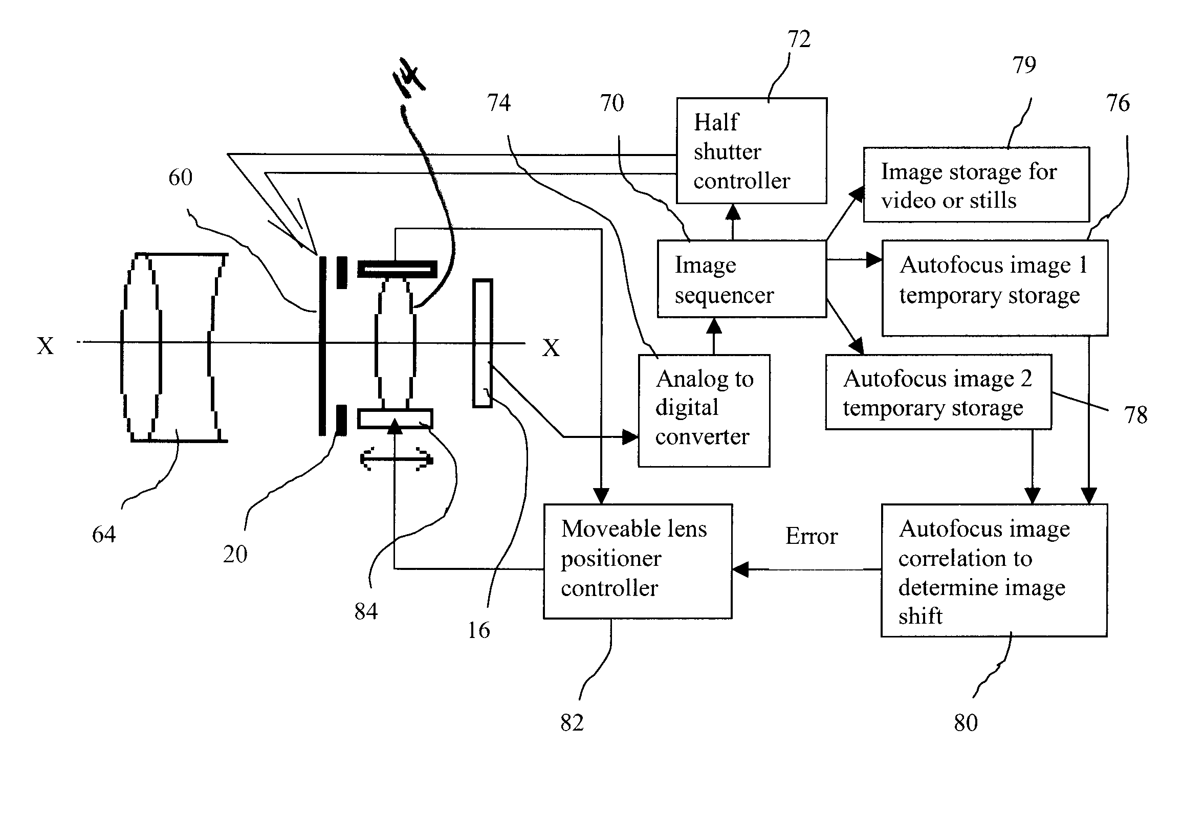
[0061]A preferred embodiment is described as an example. In this case, a high speed liquid crystal element is used as is available from LC-Tec Display (LC-TEC DISPLAYS AB, Tunavagen 281, SE-781 73 Borlänge, SWEDEN) such as model FOS-PSCT. By applying a voltage of approximately 100 volts, the element changes from white to transparent. The element is arranged in two independently controllable sections to block half of the aperture at a time (half white and half transparent) with the ability to also operate in a substantially unrestricted mode (substantially transparent in both sections) or a completely white mode (white in both sections). In addition, an imager with at least a portion of the pixels being unfiltered or panchromatic are present wherein the unfiltered or panchromatic pixels are used to capture monochrome autofocus images from wavelengths that span substantially the entire visible range of light.

[0062]The advantages of the liquid crystal element are that it is capable of ...

example 2

[0067]In a further preferred embodiment as an example, that is particularly suitable for still capture, a split aperture device is used. In this embodiment, the moveable lens is positioned at an extreme position, either at near focus or far focus positions, prior to the capture of the autofocus images, the image will be substantially out of focus and a large difference between the two autofocus images is assured. The advantage of this embodiment is that a large signal is provided for analysis to determine the moveable lens position required for best focus quality. The timing for the capture of the autofocus images and the still image would then be similar to that shown in Tables 2 and 3.

example 3

[0068]In another preferred embodiment as an example, in situations where the scene content is rapidly changing, the change of focus, frame to frame, may be faster than desired. In this case, a limit can be applied to the rate of change of the focus between frames. Each frame would still be focused individually but the change of focus between frames would not be allowed to exceed the limit. By limiting the focus change between frames, the focus changes would appear smoother in the video segment.


PUM


Abstract

A method for operating an autofocus system for focusing an image on an electronic imager includes providing an adjustable lens system defining an optical path for scene light and having at least one movable lens to focus an image of the scene onto the electronic imager; and causing a first portion of the scene light to be obscured so that the electronic imager captures a first autofocus image and causing a second different portion of the scene light to be obscured so that the electronic imager captures a second autofocus image wherein portions of the first and second autofocus images are offset. The method further includes moving the movable lens to a position so that an image to be captured will be in focus.

Description

FIELD OF THE INVENTION[0001]The present invention relates to autofocus systems for image capture devices that can be used for capturing a series of images for video or burst captures as well as still images.BACKGROUND OF THE INVENTION[0002]Autofocus in a digital camera, typically used for capturing still images and a series of still images for video segments, often uses a through the lens autofocus system based on a contrast analysis of a series of say 5-20 or more subsampled autofocus images taken with a moveable lens in different positions. Subsequently, the autofocus images are analyzed for contract and the moveable lens position that delivers the image with the highest contrast is deemed the best focus condition. The moveable lens is then returned to the position that delivered the highest contrast or an interpolated position between the at least two autofocus images before the still image is captured. Although this approach does deliver an accurate focus condition, it is slow d...

Claims


Application Information

Patent Timeline
Patent Type & Authority Applications(United States)
IPC IPC(8): G03B13/00
CPCH04N5/23212H04N23/673
Inventor BORDER, JOHN N.PALUM, RUSSELL J.PILLMAN, BRUCE H.SCHILLING-BENZ, LYNN
Owner OMNIVISION TECH INC
Why Eureka
Try Eureka