Getters for thin film battery hermetic package

Inactive Publication Date: 2008-01-03
OAK RIDGE MICRO ENERGY
View PDF7 Cites 99 Cited by
  • Summary
  • Abstract
  • Description
  • Claims
  • Application Information

AI Technical Summary

Benefits of technology

[0013]An advantage of the disclosed embodiments is that improved hermetic seals for thin film batteries having anodes that greatly expand on charging may be provided. While conventional thin film battery packages containing lithium anodes and other anodes that do not greatly expand on charging may use conventional hermetic seals, thin film battery packages that have anodes that expand over about 200 percent of th

Problems solved by technology

Liquid organic electrolytes used in conventional lithium-ion batteries pose safety problems because the electrolytes are flammable and are not tolerant to temperatures above about 130° C. The attractiveness of thin-film batteries over conventional batteries is that the electrolyte is a solid or non-flowable material rather than a liquid.
One of the challenges for thin film battery manufacturers is to provide a thin film battery having solid electrolytes that will have an extended life.
An extended life is particularly diff

Method used


Image

  • Getters for thin film battery hermetic package
  • Getters for thin film battery hermetic package
  • Getters for thin film battery hermetic package

Examples


Example

EXAMPLE 1

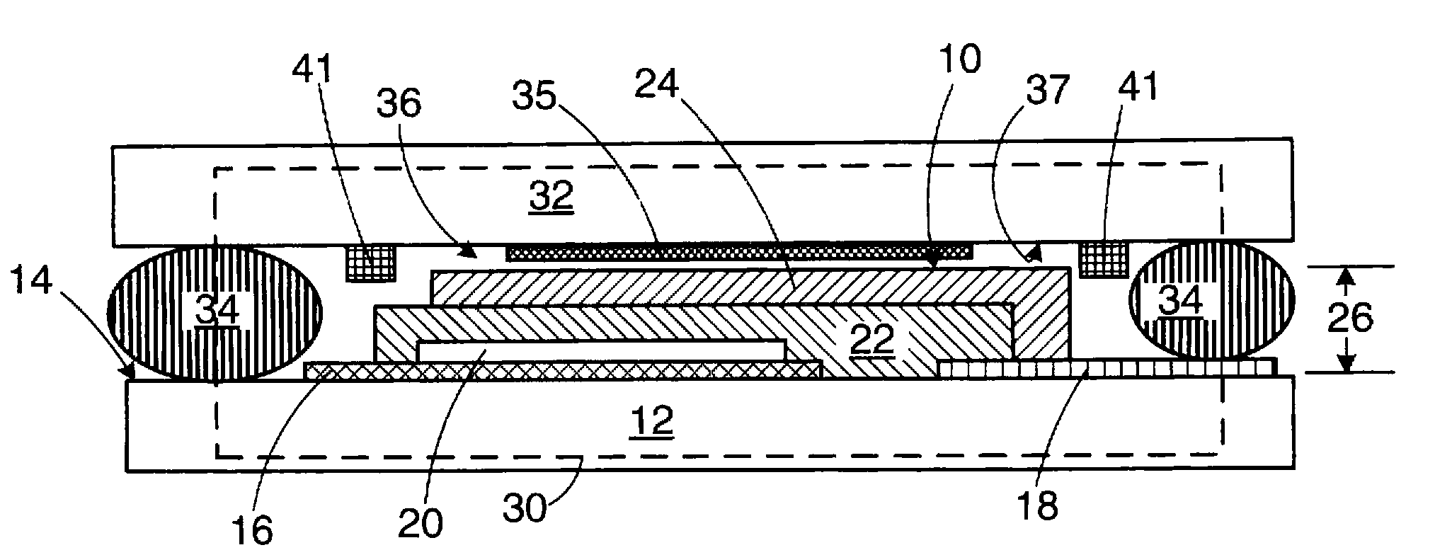
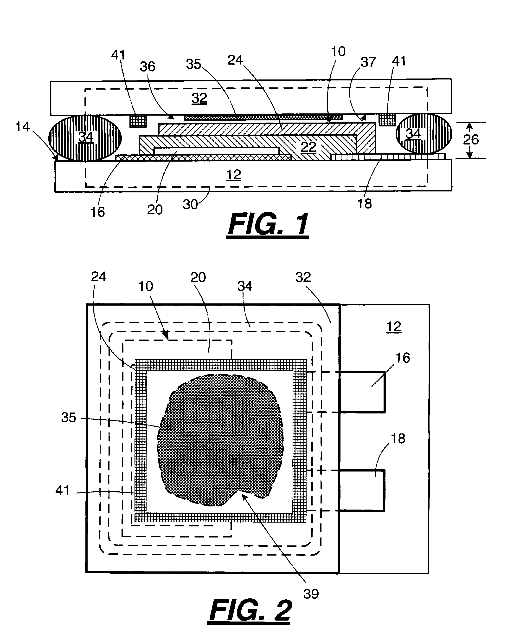
[0055]A glass plate (from SCHOTT North America, Inc., of Elmsford, N.Y.) about 4.5 inches by about 4.5 inches by about 0.008 inches is mounted on low-tack wafer tape (Z18133-7.5 from Semiconductor Equipment Corporation of Moorpark, Calif.) using a vacuum laminator. The plate is scribed into about 0.402 inch by about 0.402 inch squares to a depth of about 0.0040 inches to about 0.0045 inches using a dicing saw. The scribed glass sheet is mounted onto a substrate holder and covered with a thin sheet of stainless steel or plastic into which about 0.27 inch diameter circles have been cut to form a mask. The circles preferably include a notch or other small feature to give deposited films an asymmetric feature 39 as shown in FIG. 2. Using dc magnetron sputtering, copper is deposited to a thickness of about 1000 to about 2000 Angstroms through the mask onto the glass leaving a pattern on each lid 32 with a shape as illustrated in FIG. 2. In this example, when a lid 32 is oriented...

Example

EXAMPLE 2

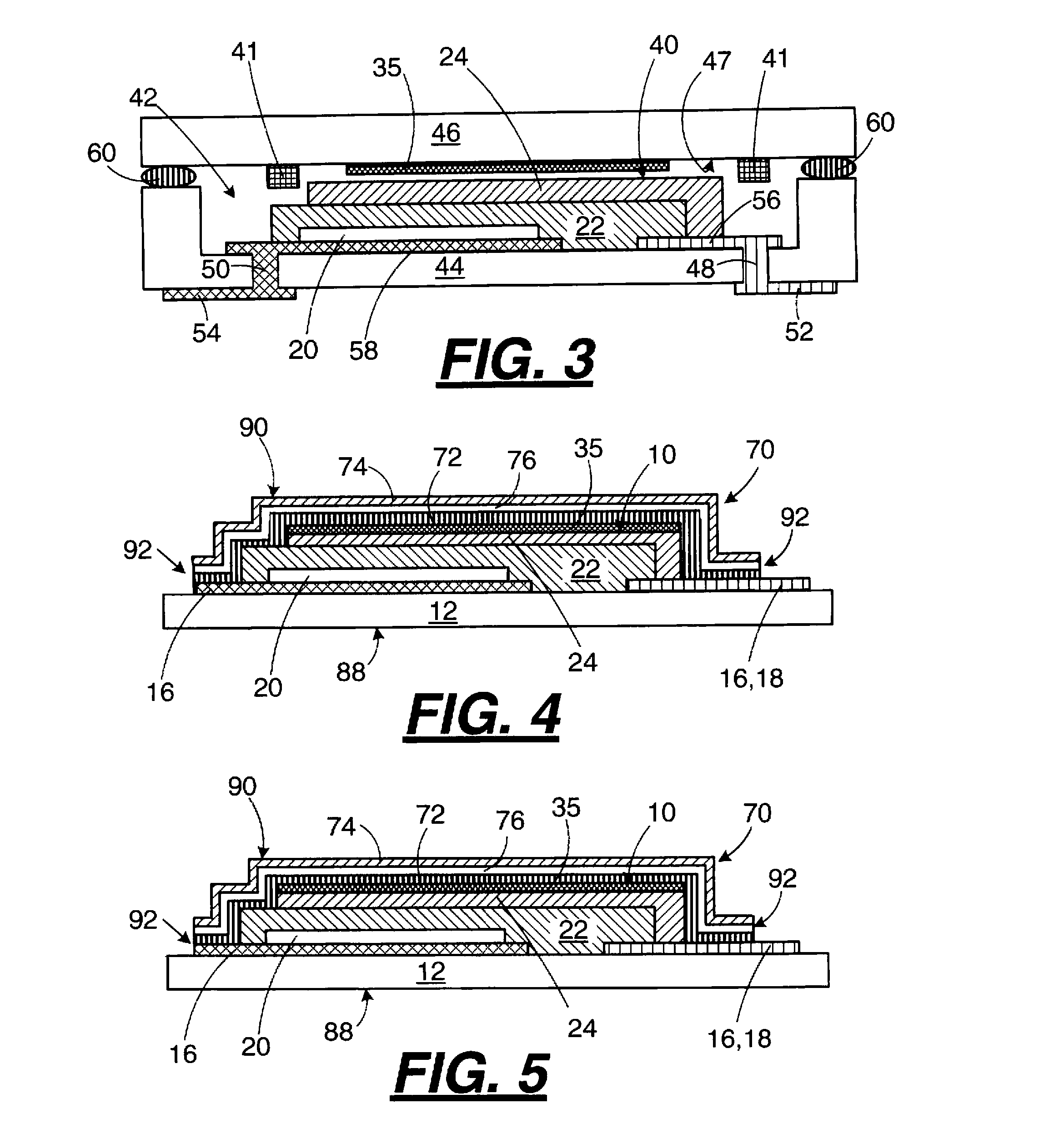
[0056]Alignment fiducials 104 illustrated in FIG. 6 are deposited onto the battery substrate 102 at different locations, near corners, edges, center, etc., during deposition of the cathode current collectors. The same pattern of fiducials 104 is deposited onto the about 4.5 inch by about 4.5 inch by about 0.008 inch glass plates mounted on wafer tape during deposition of the getter films (35 and / or 41). After dispensing adhesive lines 106 on the thin film battery substrate 102 including the outside edge of the substrate 102, the substrate 102 and glass plate are aligned to the fiducials 104 on each other using a machine vision system incorporated into a pick and place tool. Machine vision systems are available from PPT Vision, Inc., of Eden Prairie, Minn., and pick and place tools are available from Automated Production Systems, Inc., of Huntingdon Valley, Pa. Specialized tools for aligning and placing glass plates onto substrates are manufactured, for example, by Lantechni...


PUM

PropertyMeasurementUnit
Temperatureaaaaaaaaaa
Percent by atomaaaaaaaaaa

Abstract

A method for improving the useful life of a thin film lithium-ion battery containing a solid electrolyte and an anode that expands on charging and long life batteries made by the method. The method includes providing a hermetic barrier package for the thin film battery that includes an anode expansion absorbing structure and at least one film getter.

Description

RELATED APPLICATION[0001]This application is a continuation in part of application Ser. No. 11 / 162,311 filed Sep. 6, 2005, now pending.FIELD[0002]The disclosure relates to thin film batteries and in particular to improved long-life thin film battery packages including getters and methods for making improved long-life thin film battery packages.BACKGROUND AND SUMMARY[0003]Thin-film rechargeable batteries have numerous applications in the field of microelectronics. For example, thin-film batteries may provide active or standby power for microelectronic devices and circuits. Active power source applications of the thin-film battery include, for example, implantable medical devices, remote sensors, semiconductor diagnostic wafers, automobile tire sensors, miniature transmitters, active radio frequency identification (RFID) tags, smart cards, and MEMS devices. Standby power source applications of thin-film batteries include non-volatile CMOS-SRAM memory products such as memory chips for ...

Claims


Application Information

Patent Timeline
IPC IPC(8): H01M2/08H01M10/04H01M10/0525H01M10/0562H01M10/0585H01M10/36H01M50/11H01M50/119H01M50/121H01M50/124H01M50/193H01M50/197
CPCH01M2/0207Y10T29/49114H01M2/0212H01M2/0275H01M2/0277H01M2/0285H01M2/0287H01M2/08H01M2/1022H01M4/38H01M4/382H01M6/40H01M10/0436H01M10/0525H01M10/0562H01M10/0585H01M2002/0297H01M2300/0068Y02E60/122Y10T29/4911H01M2/021H01M4/386H01M4/387Y02E60/10H01M50/131H01M50/124Y02P70/50H01M50/121H01M50/11H01M50/193H01M50/197H01M50/119
Inventor BATES, JOHN B.
Owner OAK RIDGE MICRO ENERGY
Why Eureka
Try Eureka