Controlling switching mode power supply of power amplifier

Inactive Publication Date: 2008-01-03
NOKIA CORP
View PDF20 Cites 119 Cited by
  • Summary
  • Abstract
  • Description
  • Claims
  • Application Information

AI Technical Summary

Benefits of technology

[0013]Embodiments of the invention provide several advantages. The proposed solution is straightforward to implement. It allows a flexible control over the switching mode power supply. As the variation in duplex separation may be taken into account in the control of the SMPS, the radio frequency power amplifier power c

Problems solved by technology

For example, a linear regulator has a much greater power loss compared to a switching mode power supply.
However, the attenuation is not perfect and therefore the output voltage of the SMPS inherently contains a switching ripple.
The ripple increases the transmitter interference level in the antenna of the transmitter.
Especially the first harmonics of the switching frequency are troublesome in transceivers of systems that require simultaneous transmission and recept

Method used


Image

  • Controlling switching mode power supply of power amplifier
  • Controlling switching mode power supply of power amplifier
  • Controlling switching mode power supply of power amplifier

Examples


Example

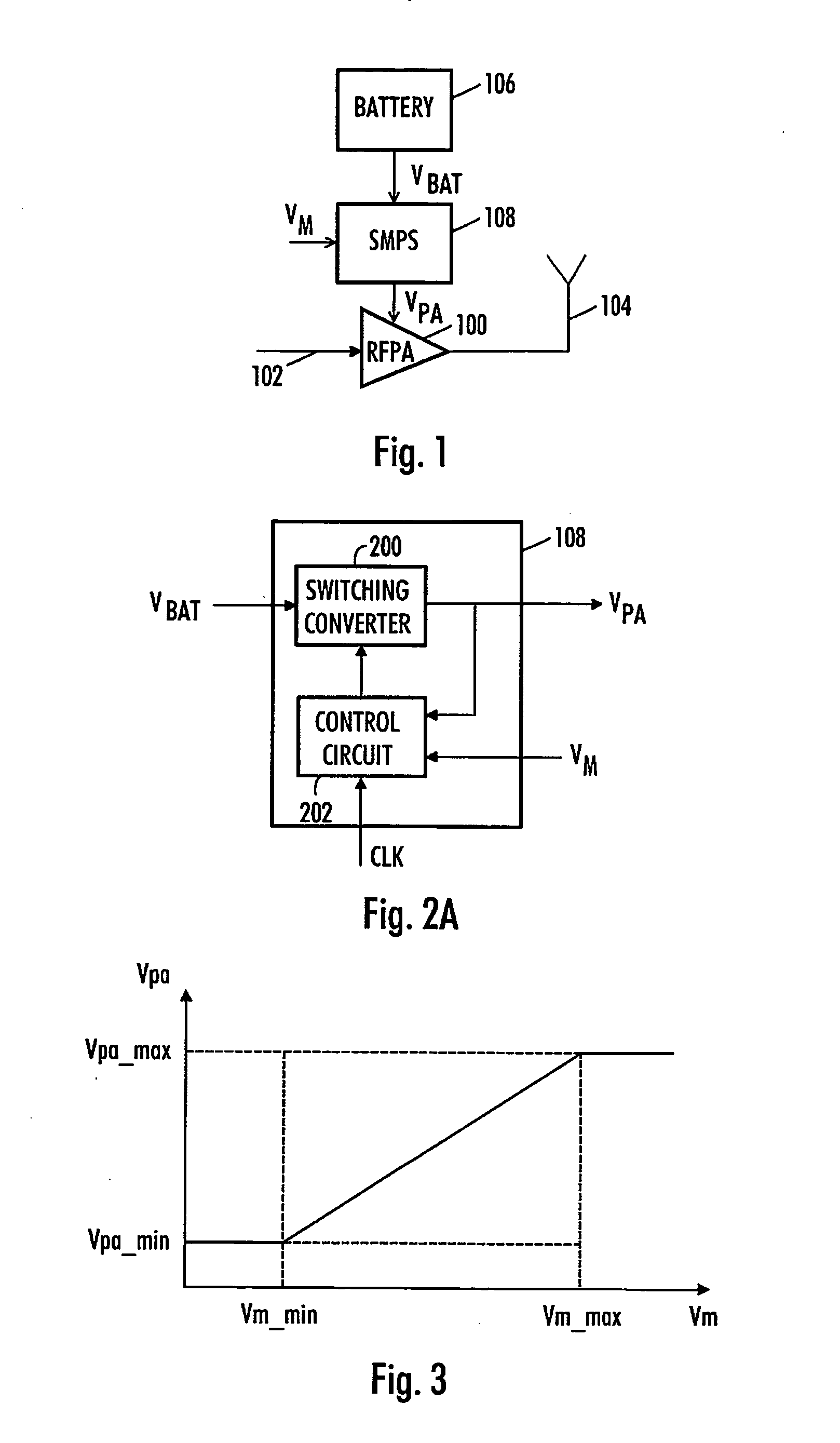
[0022]FIG. 2A illustrates an example of a switching mode power supply. The switching mode power supply 108 converts a battery voltage VBAT to a voltage level VPA as required by a power amplifier. A switching mode power supply 108 typically comprises a switching converter 200 or a power stage, and a control circuit 202 of the switching converter. In the example of FIG. 2A, the inputs to the switching mode power supply comprise a reference voltage VM and a clock signal CLK. There are many ways to implement a switching mode power supply, depending on the type of the switching converter and on the type of its control.

[0023]The switching converter may be realized as a Buck-type converter which has a step-down characteristic behavior. Thus, an output voltage VOUT of the converter is always lower than the input voltage VBAT of the converter. The converter may be realized as a Boost-type converter having a step-up characteristic behavior, where the output voltage VOUT of the converter is al...


PUM


Abstract

A radio frequency transceiver is provided. The transceiver comprises a receiver for receiving transmission at a first radio frequency and a transmitter for transmitting at a second radio frequency, and in the transmitter a power amplifier with a switching mode power supply. The transceiver further comprises a controller configured to vary switching frequency of the switching mode power supply on the basis of a frequency separation of the first and the second radio frequencies.

Description

FIELD[0001]The invention relates to switching mode power supplies generally used in radio frequency transmitters. More specifically, the invention relates to controlling the switching mode power supplies.BACKGROUND[0002]Switching mode power supplies (SMPS) are used to feed power to a power amplifier. This kind of structure is used in many portable radio transmitters between the battery and power amplifier of the transmitter, for example. The main reason for using a switching mode power supply is its good efficiency. For example, a linear regulator has a much greater power loss compared to a switching mode power supply.[0003]FIG. 1 illustrates an example of an efficient RF transmitter topology. The transmitter comprises a radio frequency power amplifier 100 which amplifies a signal 102 to be transmitted before transmission using an antenna 104. The transmitter further comprises a battery 106 which provides a battery voltage VBAT. The battery voltage is taken to a switching mode power...

Claims


Application Information

Patent Timeline
IPC IPC(8): H04B1/38
CPCH02M1/44H03F1/0238H03F3/24H03F2200/504H04W88/02H04B1/525H04B15/005H04B2215/065H04B1/0475
Inventor HAAPOJA, SAMIGRIGORE, VLADKANGASMAA, SEPPO
Owner NOKIA CORP
Why Eureka
Try Eureka