Sperm collecting apparatus

a technology of sperm collecting and ejaculation, which is applied in the direction of anti-rape devices, packaging foodstuffs, packaged goods types, etc., can solve the problems that the stimulation required for erection and ejaculation cannot be obtained, and achieve the effect of eliminating the drawback, movement or deformation of the core member inside the container, and improving the sperm collecting

Active Publication Date: 2008-01-03
TENGA
View PDF3 Cites 28 Cited by
  • Summary
  • Abstract
  • Description
  • Claims
  • Application Information

AI Technical Summary

Benefits of technology

[0041] By providing the cut line serving as a check valve in a distal end portion of the core member, air that tends to be accumulated inside the core member can be removed without delay at a time of insertion and rubbing of a penis. As a result, the contact is made tighter, so that a sperm collecting effect is improved.
[0042] Further, since the unused collecting apparatus is disposed upright with the opening side of the container facing downwardly such that the lubricating liquid (lotion) accumulates on the core member inlet side when the unused collecting apparatus is stored or displayed, it is made possible to insert his penis smoothly as it is when the cap is opened and the lubricating liquid is prevented from leaking from the insertion port of the core member.
[0043] Further, it is able to eliminate the drawback that due to repetitive abutting of a peripheral edge of an opening portion of the container main unit on a proximal portion of a user's penis or skin around his penis during use of the container main unit, a body portion of the user on which the peripheral edge abuts is damaged or the user feels discomfort.
[0044] Further, since the intermediate portion of the container is formed in a small diameter so that movement or deformation of the core member inside the container can be prevented, buckling of the core member can be prevented and a positioning easiness can be improved.
[0045] S

Problems solved by technology

Furthermore, another object is to conduct degassing without delay at a time of insertion and rubbing of a penis in order to eliminate the drawback due to air accumulating between a distal end of the penis and the inner depth portion of the core member when the penis is forcibly inserted

Method used


Image

  • Sperm collecting apparatus
  • Sperm collecting apparatus
  • Sperm collecting apparatus

Examples


Embodiment Construction

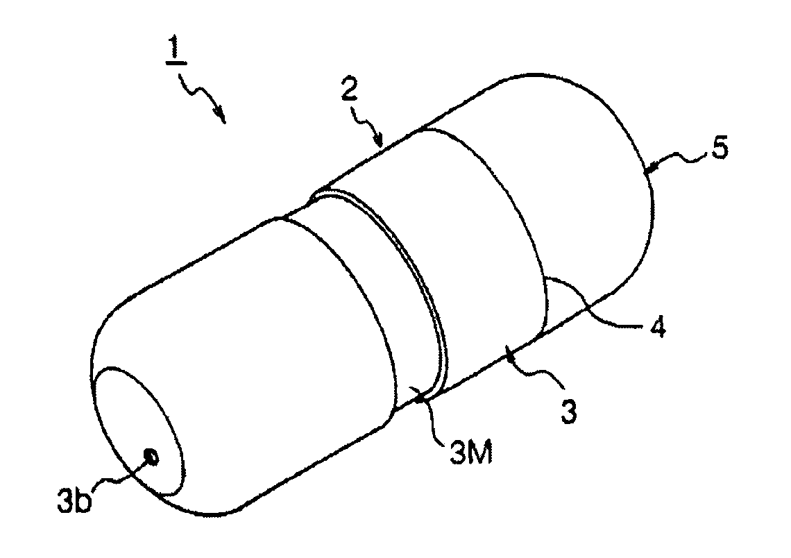
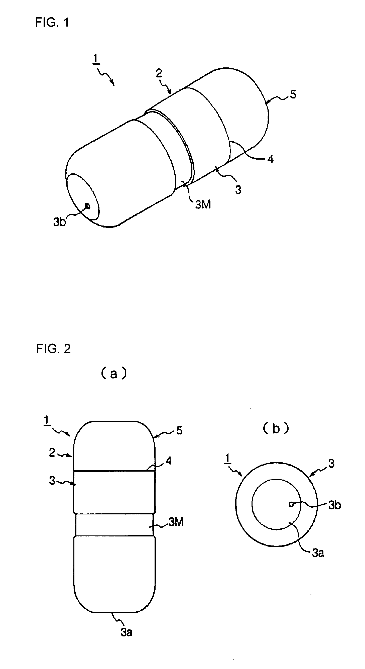
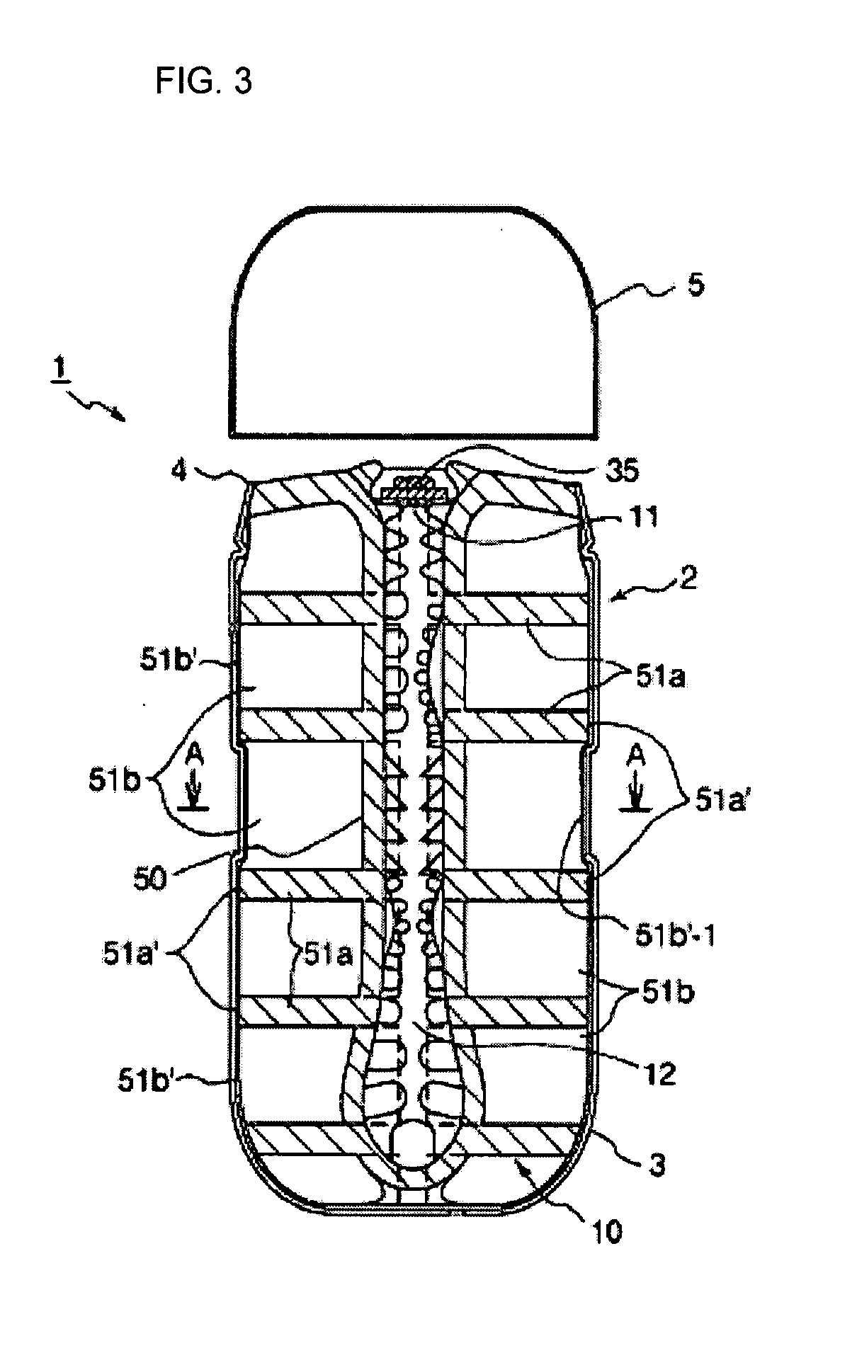
[0057]FIG. 1 is an appearance perspective view of a sperm collecting apparatus according to one embodiment of the present invention, FIGS. 2(a) and 2(b) are a front view of the sperm collecting apparatus and a bottom view thereof, FIG. 3 is a vertical sectional view of the sperm collecting apparatus, FIGS. 4(a) and 4(b) are an exploded perspective view of respective constituent elements and an appearance perspective view of a core member, and FIG. 5 is a sectional view of the sperm collecting apparatus taken along line A-A in FIG. 3.

[0058] The sperm collecting apparatus 1 includes a container 2 having container main unit 3 whose one end in a longitudinal direction is opened thereof and which has a small-diameter portion 3M at a proper portion (an intermediate portion) on an outer peripheral face, and a cap 5 that is attached to and detached from an opening portion 4 of the container main unit 3 to close and open the opening portion, and a core member 10 made from a gel-like resin, ...


PUM


Abstract

A sperm collecting apparatus is provided and includes a container including a cylindrical container main unit that has an opening portion on at least one end face in a longitudinal direction thereof and a cap that is attached to and detached from the opening portion of the container main unit to close and open the opening portion, and a core member which is accommodated in said container and has an insertion room extending from an insertion port at one end face in a longitudinal direction therein. The core member includes a core main unit having said insertion port and the insertion room and a plurality of ribs provided upright from an outer face of the core main unit to cross one another, and sealed rooms are formed through the outer face of the core main unit.

Description

TECHNICAL FIELD [0001] The present invention relates to a sperm collecting apparatus, and in particular relates to an improvement of conventionally-used sperm collecting apparatuses based on social demands, such as medical researches, demands for medical treatment, prevention of sex-related crimes, antiprostitution activities, and prevention of spreading of venereal diseases, and the like. BACKGROUND OF THE INVENTION [0002] Various sperm collecting apparatuses for collecting men's sperm have been proposed for the necessities of medical research or treatment. For example, a sperm collecting apparatus is used for medical needs such as examination of sexual function of a husband from the sperm collected for examination of the cause of marital infertility, or treatment of sexual dysfunction, reservation and storage of the sperm for artificial insemination. Simple sperm collecting apparatuses that can be conventionally available at a low price and that do not cause sanitary or health pro...

Claims


Application Information

Patent Timeline
IPC IPC(8): A61M1/00
CPCA61B10/0058A61H19/32A61F5/0096A61J1/05
Inventor MATSUURA, TSUTOMU
Owner TENGA
Why Eureka
Try Eureka