

Occupant Protection Device
a technology for protecting devices and occupants, applied in the direction of electric devices, vehicle seats, special data processing applications, etc., can solve problems such as failure to appropriately protect occupants
- Summary
- Abstract
- Description
- Claims
- Application Information
AI Technical Summary
Benefits of technology
Problems solved by technology
Method used
Image

Examples
first embodiment
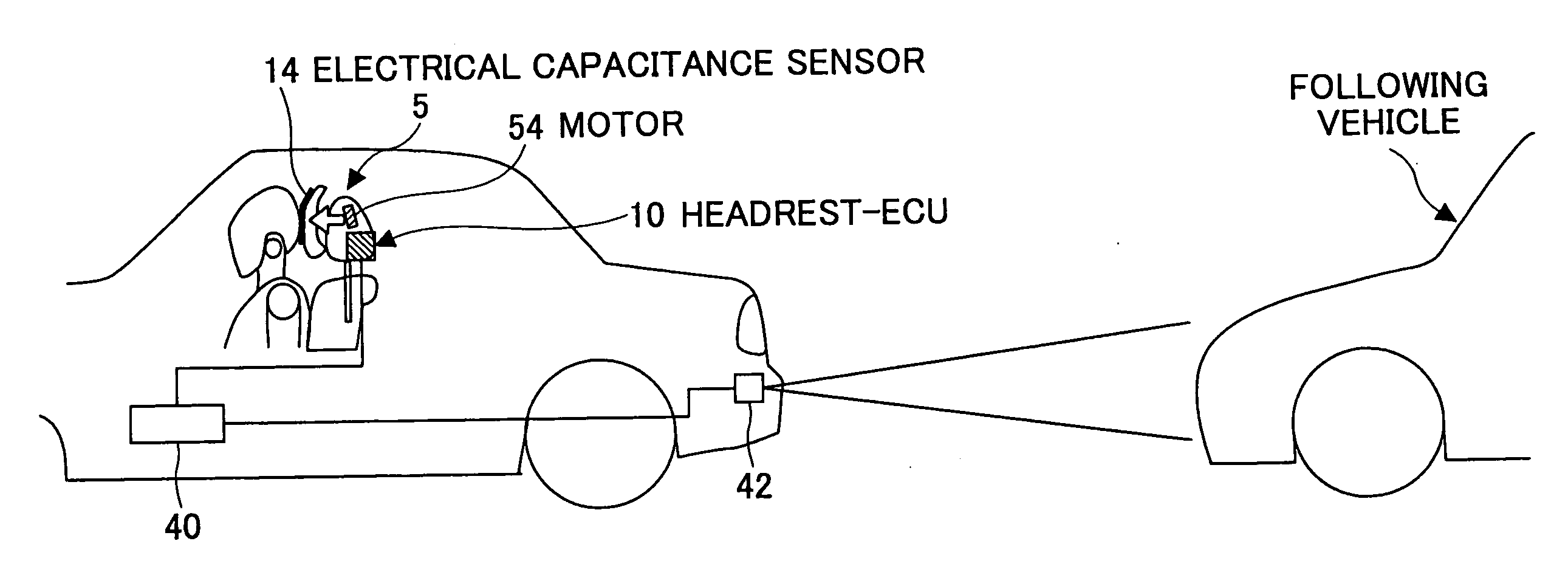
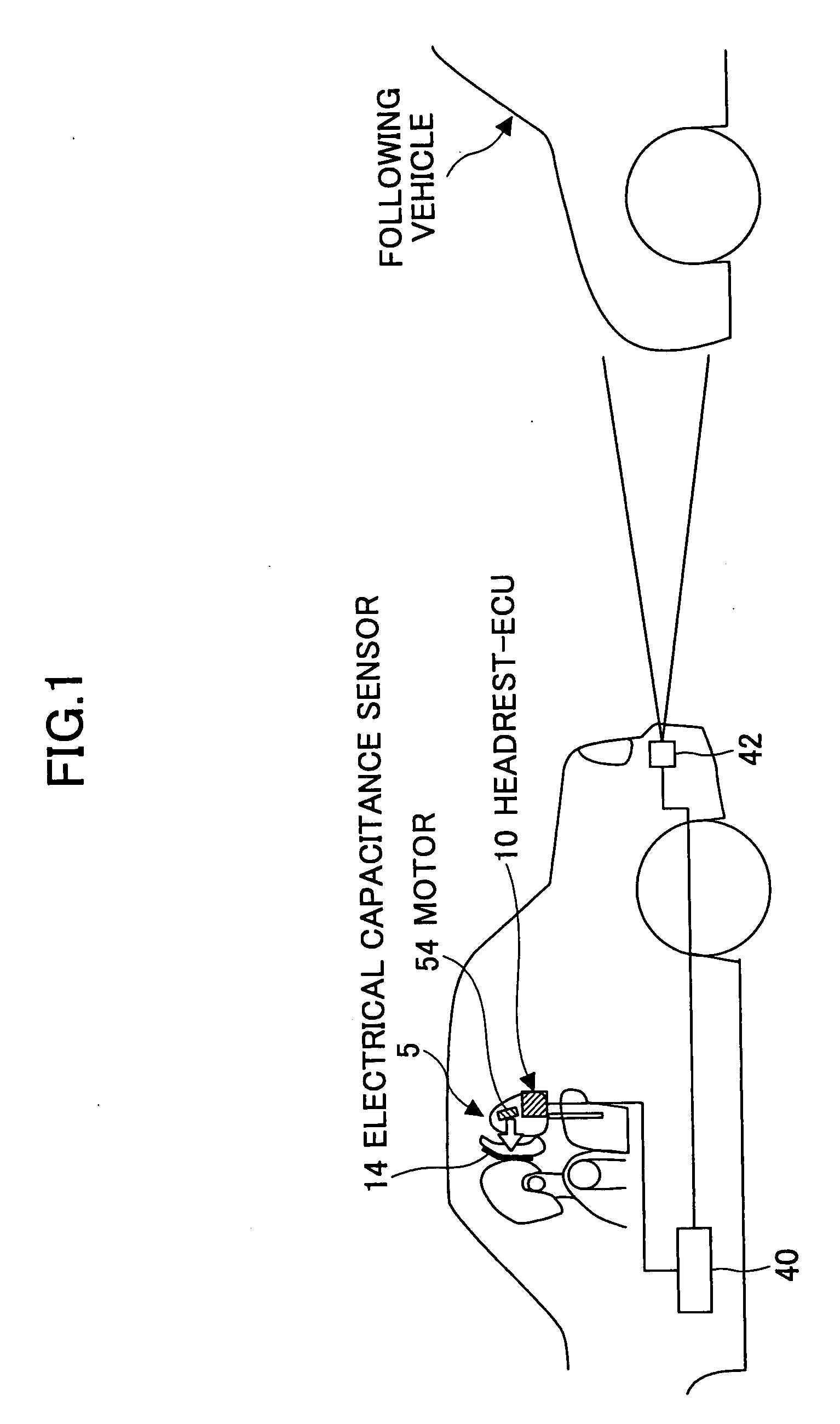
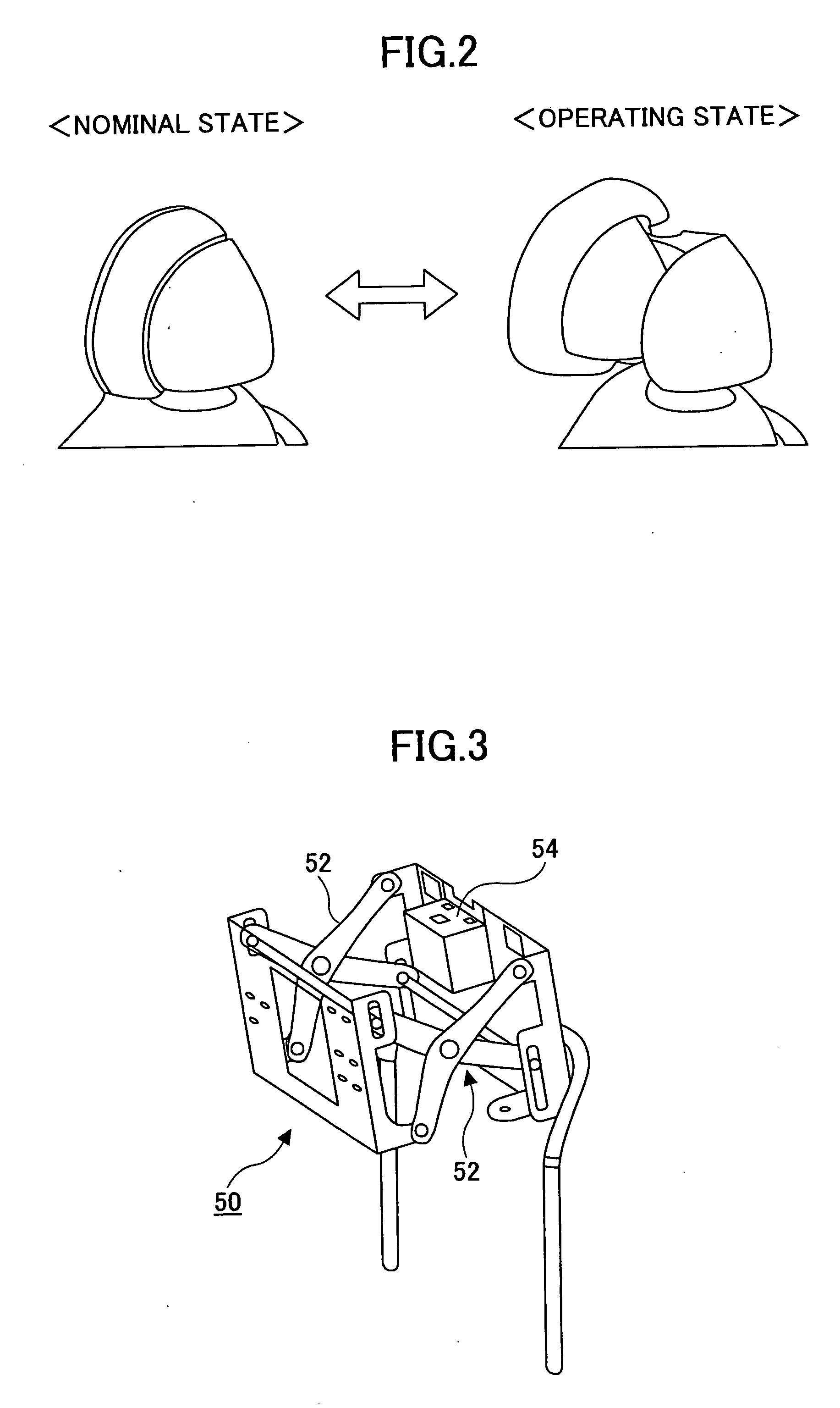
[0037]FIG. 1 is a schematic system diagram of a vehicle occupant protection device according to an embodiment of the present invention. In FIG. 1, the respective elements are illustrated in a picture of the vehicle viewed from a side of the vehicle. FIG. 2 is a diagram showing a headrest 5 in its normal state and the headrest 5 in a state after having moved forward. FIG. 3 is a perspective view of a driving mechanism for the headrest 5. It is noted that a vehicle in which the vehicle occupant protection device is installed is often referred as to “a base vehicle” hereafter.
[0038] The vehicle occupant protection device according to the present embodiment is mainly comprised of an electric control unit 10 (referred as to “headrest-ECU 10” hereafter). The headrest-ECU 10 is implemented by a micro computer comprising a CPU, a ROM, a RAM etc., inter-connected by a bus (not shown), as is the case with other ECUs.
[0039] The headrest 5 is provided on the top of a seat at a level of the ba...
second embodiment
[0058] Next, the vehicle occupant protection device according to the second embodiment of the present invention is explained with referring to FIG. 6. FIG. 6 is a functional block diagram illustrating an algorithm for stopping the forward movement of the headrest which is executed by a headrest-ECU 10 according to the second embodiment of the present embodiment. Hereafter, only the configuration unique to the second embodiment is explained, assuming that the other configuration is the same as that of the first embodiment.
[0059] In the present embodiment, an operating voltage control section 56 is provided for controlling the operating voltage (or the operating current) so as to be a substantially constant value, as shown in FIG. 6. This is because in an actual vehicle a power source (i.e., a battery) for supplying the operating voltage of the DC-motor 54 also functions as a supply source for other various loads (a starter, an audio device, an air-conditioning device, head lamps, fo...
third embodiment
[0061] Next, the vehicle occupant protection device according to the third embodiment of the present invention is explained with reference to the figures from FIG. 7. FIG. 7 is a functional block diagram illustrating an algorithm for stopping the forward movement of the headrest which is executed by a headrest-ECU 10 according to the third embodiment of the present embodiment. Hereafter, only the configuration unique to the third embodiment is explained, assuming that the other configuration is the same as that of the first embodiment.
[0062] In the example illustrated in FIG. 7, the predetermined threshold As0 is corrected according to the operating voltage Vm of the DC-motor 54. In the illustrated example, the predetermined threshold As0 is multiplied by the operating voltage Vm. The corrected predetermined threshold As0′ (=As0×Vm) is compared to the capacitance count change gradient B. The purpose of this correction is described later. If the capacitance count change gradient B e...
PUM
 Abstract
Description
Claims
Application Information