Sensorless Measurement of Positioning Travel, Especially on an Electromotively Operated Parking Brake

a technology of positioning travel and sensor, which is applied in the direction of program control, complex mathematical operations, computation using non-denominational number representation, etc., can solve the problems of high cost of fitting a hall or another sensor, and disadvantage of being susceptible to faults

Inactive Publication Date: 2008-01-03
LUCAS AUTOMOTIVE GMBH
View PDF6 Cites 7 Cited by
  • Summary
  • Abstract
  • Description
  • Claims
  • Application Information

AI Technical Summary

Benefits of technology

[0010] In a further embodiment, which can be combined with the above embodiments, the motor model additionally takes account of a loading torque in that the torque is preferably determined from a measured motor current, with an efficiency factor of an electrical part of the electric motor being taken into account.

Problems solved by technology

However high costs are incurred by fitting a Hall or another sensor.
However these have the disadvantage of being susceptible to faults.

Method used


Image

  • Sensorless Measurement of Positioning Travel, Especially on an Electromotively Operated Parking Brake
  • Sensorless Measurement of Positioning Travel, Especially on an Electromotively Operated Parking Brake
  • Sensorless Measurement of Positioning Travel, Especially on an Electromotively Operated Parking Brake

Examples


Embodiment Construction

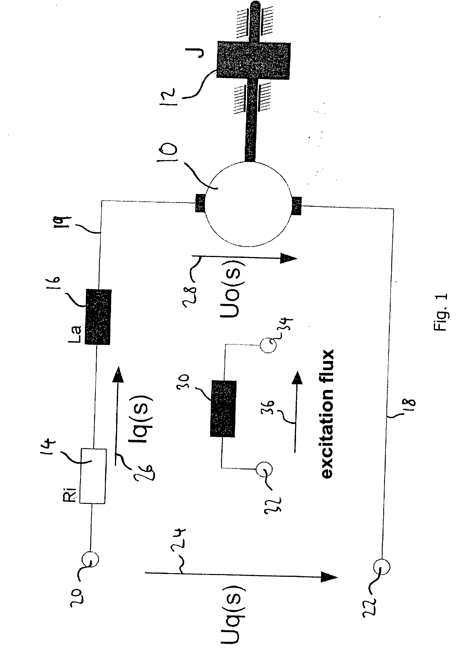
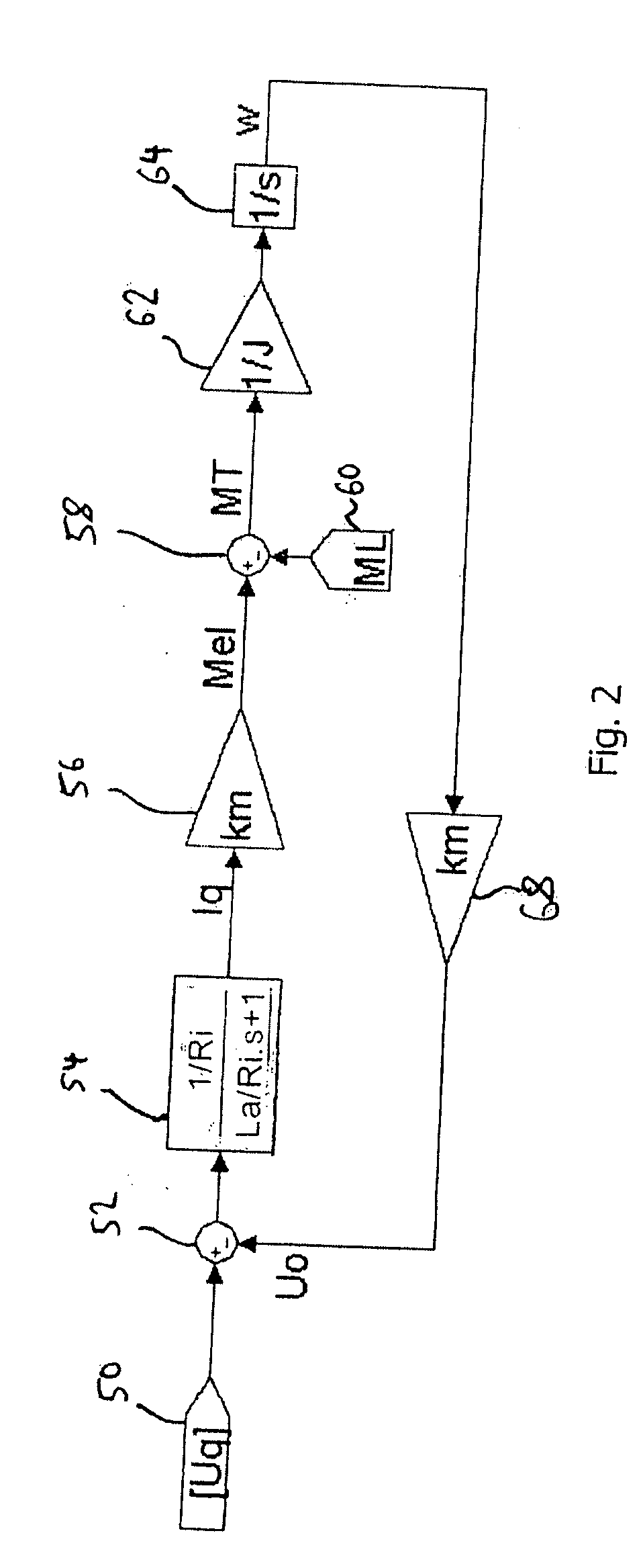
[0031] In order to establish a motor model for a D.C. motor which is excited by a permanent magnet, the equivalent circuit diagram of the separately excited D.C. motor can generally be taken as a starting point.

[0032] The following variables are used in the following:

Uq applied operating voltage (terminal voltage)

Uo induced voltage in the motor on account of the rotational movement

Ri armature resistance

La armature coil inductance

Iq armature current

Imess measured motor current

ψd magnetic flux

Km motor constant (indicated by the manufacturer, unit: Nm / A)

s Laplace variable

ω angular speed of the motor (angular frequency)

J moment of inertia of the load

Mel electrically generated driving torque

ML load torque on the motor shaft

MT acceleration torque

Md damping torque

c proportionality constant

Ta armature time constant

Mfr∞ no-load friction torque (unit: Nm)

I∞ no-load current (unit: A)

Ω∞ no-load angular speed (unit: rad / s)

b damping constant (unit: Nm sec / r...


PUM


Abstract

The invention relates to a method for establishing the position of an actuating unit which is operated by an electric motor, in which a motor speed is determined from a motor model, the speed is integrated over a period of time and the position of the actuating unit is determined by multiplying the result of the integration by a proportionality factor. The motor model takes account of afterrunning of the electric motor at the instant of switch-off. The invention also relates to actuating units, brakes, pumps and transmissions for which the method can be used.

Description

CROSS-REFERENCE TO RELATED APPLICATIONS [0001] This application is a National Stage of International Application No. PCT / EP2005 / 013486 filed Dec. 15, 2005, the disclosures of which are incorporated herein by reference, and which claimed priority to German Patent Application No. 10 2004 061 917.4 filed Dec. 22, 2004, the disclosures of which are incorporated herein by reference.BACKGROUND OF THE INVENTION [0002] The invention relates to a method for establishing the position of an actuating unit which is operated by an electric motor. The invention also relates to brakes, pumps and transmissions in which actuating units of this kind are used. [0003] In the case of, for example, an electronic parking brake (EPB) which is operated by an actuating unit the motor speed is as a rule currently measured by sensor technology (for instance by means of a Hall sensor). The number of detected revolutions (or of pulses delivered by the Hall sensor) multiplied by a motor constant gives the travel ...

Claims


Application Information

Patent Timeline
Patent Type & Authority Applications(United States)
IPC IPC(8): H02P7/285G06F17/10G06F9/00
CPCH02P7/2805H02P7/2855H02P7/2815
Inventor LINDEN, CHRISTOPHKELLER, MICHAEL
Owner LUCAS AUTOMOTIVE GMBH
Why Eureka
Try Eureka