
Compression Method for Managing the Storing of Persistent Data From a Non-Volatile Memory to a Backup Buffer

a compression method and persistent data technology, applied in memory systems, instruments, electric digital data processing, etc., can solve the problems of not considering a transaction method for storing persistent data, unable to perform more than 100,000 “secure updating", and the value of persistent data is left in an inconsistent state, so as to avoid fragmented storage of persistent data and avoid overflow of the backup buffer

Inactive Publication Date: 2008-01-03
STMICROELECTRONICS INT NV
View PDF8 Cites 216 Cited by
  • Summary
  • Abstract
  • Description
  • Claims
  • Application Information

AI Technical Summary

Benefits of technology

[0028] Advantageously, one or more address entries not marked as erasable may be copied from a first address page to a second address so that the first address page is erased and may be used for storing additional persistent data. This may avoid an overflow of the Backup buffer even when the Backup buffer size is limited. Advantageously, when a large number of address pages are involved in the storing of persistent data, the compression method may compress them inside a subset of the address pages, and release as many address pages as possible and avoiding a fragmented storage of persistent data.

Problems solved by technology

If an accidental electrical deactivation occurs during an application execution, specifically during an updating operation of persistent data, it is possible that the value of persistent data is left in an inconsistent state that could compromise, completely or partially, the functioning of the electronic device in the successive power-on sessions.
However, they do not consider a transaction method for storing persistent data also in case of other unexpected events, such as those events not determined by a power off, for example.
This limitation has impact on the implementation of the method for driving the Backup buffer, as any “Secure Update” involving a number of secure writing operations has the side effect of a further writing in the Backup buffer.
Even if the device is guaranteed for 100,000 writing operations on each single byte of the non-volatile memory, the electronic device cannot perform more than 100,000 “Secure updating”, even on different memory bytes, because in opposite cases the bytes already stressed in the Backup buffer could be damaged.
More particularly, it is not possible to erase single bits within a memory region.
The same problem affects the updating operation because in such memories a writing operation requires first an erase operation to set the memory region in a “ready to be written” state.
When an unexpected event such as an accidental electrical power off occurs, because of the granularity issue, not only the bits involved in the actual write operation but all the bytes that belong to the memory regions involved in the update operation, are affected by this problem.
In fact, while the value involved in the “Non-atomic update” and stored in the non-volatile memory could be deliberately left in a partially modified state because of not belonging to a “Secure Update”, it is not acceptable that the same happens for adjacent bits that are involved in the memory portions erasing only for granularity issue.
For these reasons, the intensive use of the Backup buffer may determine the failure of an update operation due to an out of memory reason, because the Backup buffer space is not sufficient to store all the memory regions.
Moreover, a large amount of erase / write operations inside the Backup buffer, intended to release its Backup entries for avoiding overflow, may limit the life-time of the Backup buffer.

Method used


Image

  • Compression Method for Managing the Storing of Persistent Data From a Non-Volatile Memory to a Backup Buffer
  • Compression Method for Managing the Storing of Persistent Data From a Non-Volatile Memory to a Backup Buffer
  • Compression Method for Managing the Storing of Persistent Data From a Non-Volatile Memory to a Backup Buffer

Examples


Embodiment Construction

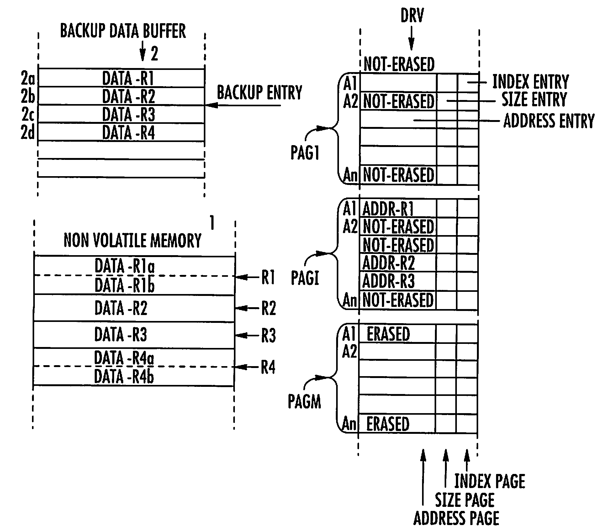
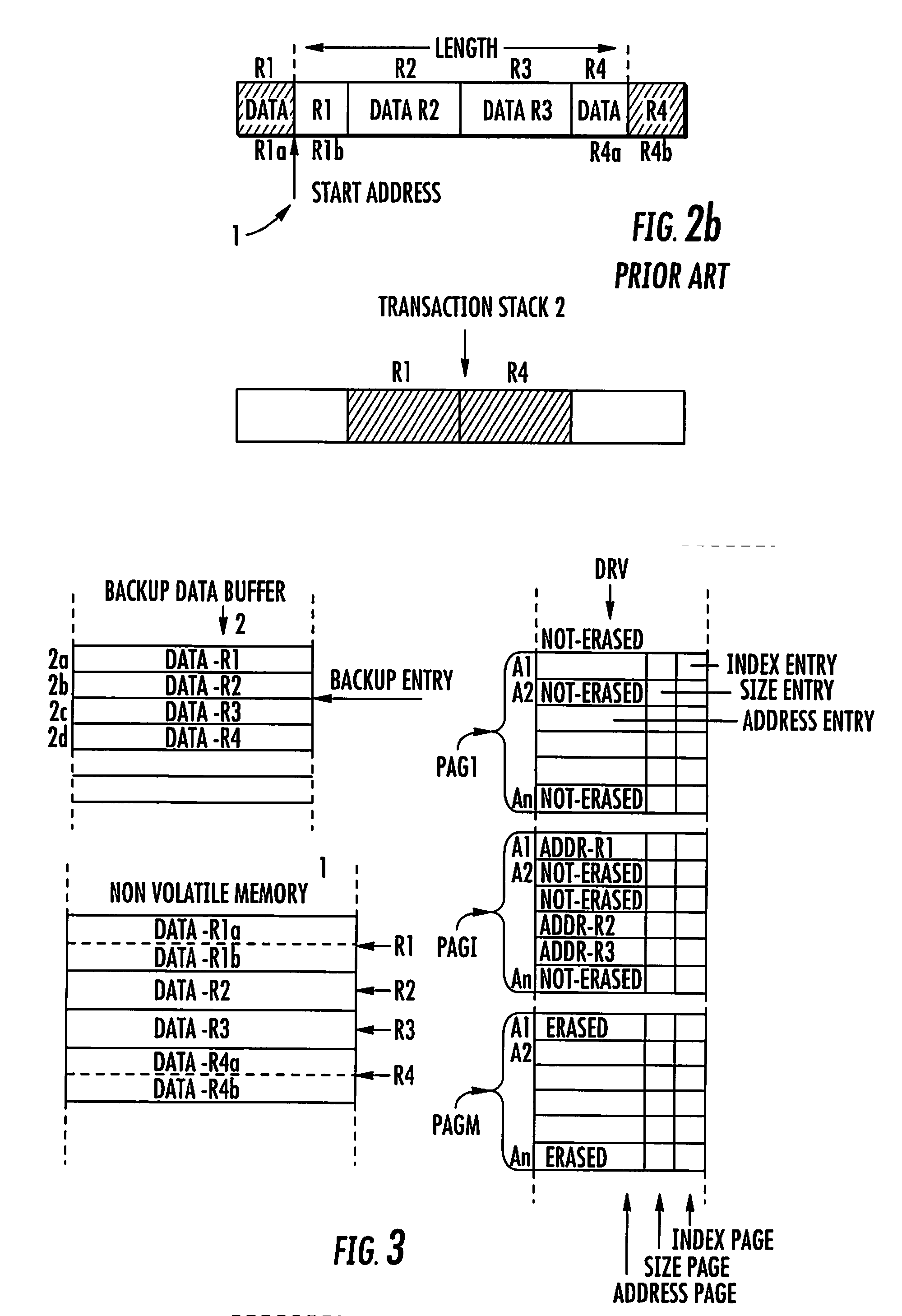
[0036] With more specific reference to FIG. 3, a non-volatile memory device 1 comprises a plurality of memory portions R1-R4 that are provided for respectively storing persistent data data-R1 . . . data-R4. In the same figure a Backup buffer 2 is also represented, and comprises a plurality of Backup entries 2a-2d for storing the persistent data data-R1 . . . data-R4 during update operations op1, op2.

[0037] More particularly, during the execution of such update operations op1, op2, a compression method drives the storing of persistent data data-R2, data-R3 contained in memory portions R2, R3 inside the Backup entries 2a, 2b of the Backup buffer 2. More particularly, an address Addr-R2, Addr-R3 wherein the memory portions R2, R3 are stored in a non-volatile memory 1 is recorded in an address entry A1, A2 included in an address page pag1 of a driver buffer drv.

[0038] The driver buffer drv comprises a plurality of address pages pag1, pag2, pagm. Each one sized equal or as a multiple o...


PUM


Abstract

A compression method for a backup data buffer includes a plurality of backup entries for storing persistent data of a non-volatile memory device during at least one update operation. An address of the persistent data in the non-volatile memory device is stored in a driver buffer including address pages. Each address page includes address entries. The compression method includes the functions for marking as erasable an address entry included in a first address page of the driver buffer when the at least one update operation on the persistent data is completed. Address entries not marked as erasable or non-erasable are copied from the first address page to a second address page of the driver buffer. The second address page contains address entries not marked as erasable. The first address page is erased for rendering it ready to be written. The content of the second address page is written to the first, and the second address page is for future writings.

Description

FIELD OF THE INVENTION [0001] The present invention relates to a compression method for managing the storing of persistent data from a volatile memory device to a Backup buffer comprising a plurality of Backup entries before the execution of at least one update operation that involves the persistent data. More particularly, if an unexpected event occurs, the value of the persistent data involved in the at least one update operation is to be restored in a consistent state from the Backup buffer. BACKGROUND OF THE INVENTION [0002] A non-volatile memory, such as a Flash memory or an EEPROM memory, is used in an electronic device to store non-volatile data. Such non-volatile data is also indicated as persistent data because their content may be variable during the programming phases of the electronic memory device, but their values need to be preserved during power off. [0003] More particularly, the non-volatile memory assures that the value of persistent data is not lost after a regula...

Claims


Application Information

Patent Timeline
IPC IPC(8): G06F12/16
CPCG06F11/1433
Inventor SEPE, PAOLODI COSMO, LUCA
Owner STMICROELECTRONICS INT NV
Learn More