Small volume liquid handling system

a liquid handling system and small volume technology, applied in the field of automatic methods and systems for small volume liquid dispensing, can solve the problems of piezo dispensers with problems such as clogging, tissue damage, and sensitivity to barometric pressure, and achieve the effects of reducing the risk of contamination, reducing and improving the efficiency of liquid dispensing

Inactive Publication Date: 2008-01-10
BIOMACHINES
View PDF0 Cites 40 Cited by
  • Summary
  • Abstract
  • Description
  • Claims
  • Application Information

AI Technical Summary

Benefits of technology

[0056] (3) an interface tube located upstream of the solenoid valve containing a small volume of prime fluid so that a certain small volume of fluid is maintained above and below the solenoid valve during dispensing, so that during operation the dispense fluid is stored in the reservoir tubing and is not allowed to enter the solenoid valve in order to prevent clogging and physically or chemically interacting with the internal components of the valve.

Problems solved by technology

Historically, small volume liquid handling applications were limited to dispensing in pre-defined row column matrices embodied by 96, 384, and 1536 well microtiter plates or higher density arrays.
Contact printing can work well with small volumes of liquid, but because of physical contact can damage the surface of a substrate or can destroy an object on the surface of a substrate, such as tissue.
Theoretically, piezo based liquid handling techniques should be competitive with contact printers in microarray dispensing; however, piezo dispensers have issues related to clogging, cross contamination, sensitivity to barometric pressure, and other practical issues, especially incompatibility with certain chemical and biological materials.
Existing liquid handlers are limited by reliability and ease-of-use issues which negatively impact both performance and function.
The performance and reliability of a solenoid valve based dispenser has heretofore generally been limited to reliable dispensing over the range of 10's to 100's of nanoliters.

Method used


Image

  • Small volume liquid handling system
  • Small volume liquid handling system
  • Small volume liquid handling system

Examples


Embodiment Construction

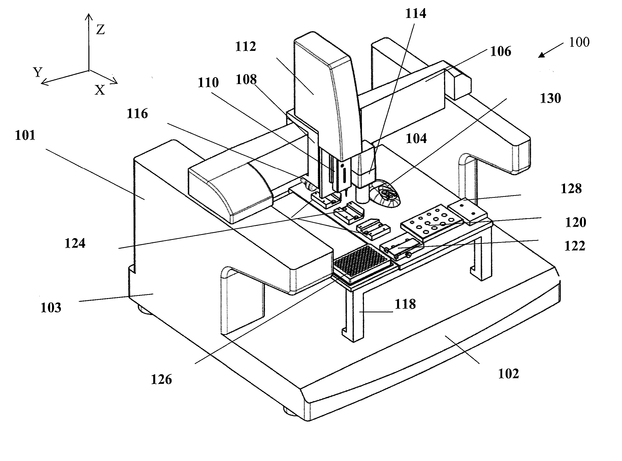
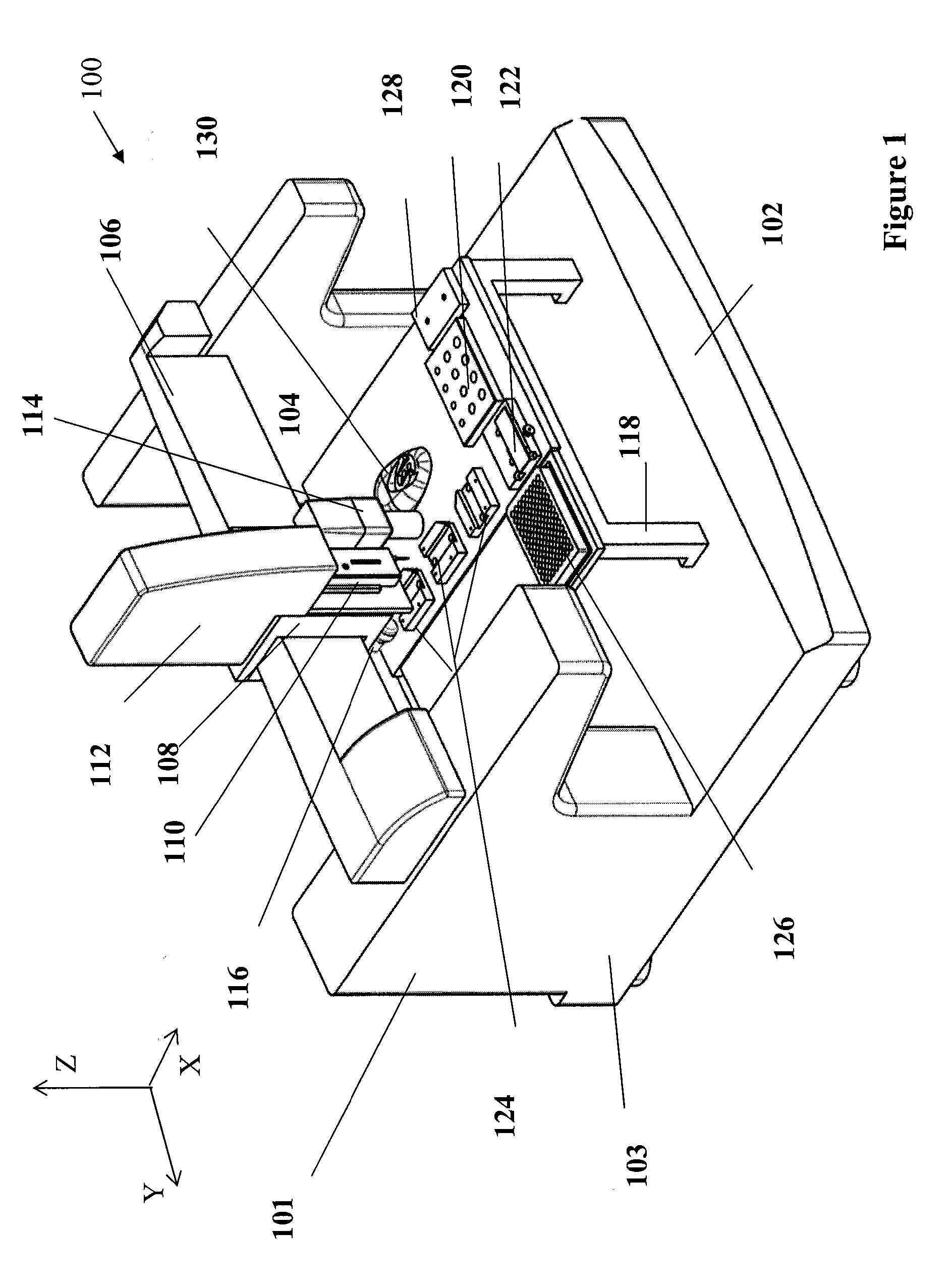
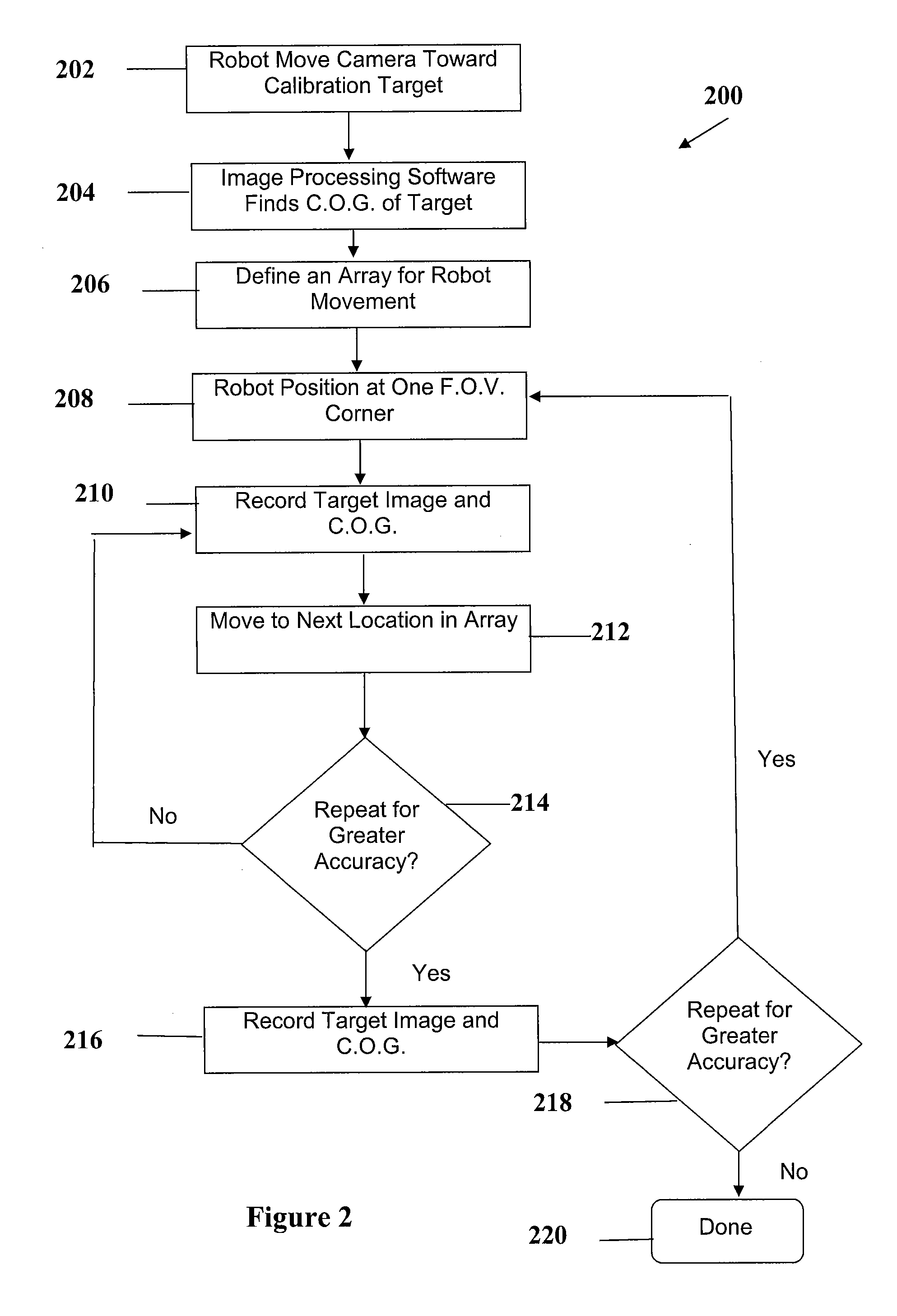
[0081] The present invention will be described in terms of specific, example embodiments. It is to be understood that the invention is not limited to the example embodiments disclosed. It should also be understood that not every feature of the devices or methods described are necessary to implement the invention as claimed in any particular one of the appended claims. Various elements, steps, processes, and features of various embodiments of devices and processes are described in order to fully enable the invention. Throughout this disclosure, where a process or method is shown or described, the steps of the method may be performed in any order or simultaneously, unless it is clear from the context that one step depends on another being performed first.

[0082] In the Figures herein, unique features receive unique reference numerals, while features that are the same in more than one drawing receive the same reference numerals throughout. Further, certain terms of orientation may be u...


PUM


Abstract

The present invention relates to non contact, vision (imaging device / camera) guided, vision-enabled, solenoid valve liquid dispensing systems and methods of using same for automation of complex laboratory workflows and especially useful for a variety of biomedical and other applications including automated front-end sample preparation for matrix assisted laser desorption / ionization (MALDI) mass spectrometry analysis.

Description

CROSS REFERENCE TO RELATED APPLICATIONS [0001] This application claims priority to U.S. Provisional Application No. 60 / 781,932 filed on Mar. 13, 2006 and U.S. Provisional Application No. 60 / 811,319 filed on Jun. 6, 2006, the contents of which are hereby incorporated herein by reference for all purposes.BACKGROUND OF THE INVENTION [0002] 1. Field of the Invention [0003] This invention relates to automated methods and systems for small volume liquid dispensing, and more particularly, to vision (imaging device / camera) guided and solenoid valve dispensing systems and methods usable for a variety of biomedical and other applications. [0004] 2. Description of Related Art [0005] Nanoliter liquid handling has become an important technology area because increasingly there are requirements for handling very small volumes of a variety of liquids in high throughput drug discovery, medical diagnostics, basic scientific research, and many other biomedical applications. Historically, small volume ...

Claims


Application Information

Patent Timeline
Patent Type & Authority Applications(United States)
IPC IPC(8): B67D5/12B67D5/14B67D7/12B67D7/14
CPCB01L3/0268B01L2400/0487B01L2400/0666G01N35/1016G02B21/36G01N2035/00158G01N2035/1039G02B21/16G01N35/1074
Inventor DAI, ZHENG-SHANWANG, XUE-FENGSHERIDAN, RICHARD BRINSLEY III
Owner BIOMACHINES
Why Eureka
Try Eureka