Voltage controlled oscillator

Inactive Publication Date: 2008-01-10
LAPIS SEMICON CO LTD
View PDF5 Cites 24 Cited by
  • Summary
  • Abstract
  • Description
  • Claims
  • Application Information

AI Technical Summary

Benefits of technology

[0040]The adjustment voltage signal adjusts the relationship between the control voltage signal and the capacitances of the first and second MOS varactors. This relationship can be plotted as a curve in a two-dimensional Cartesian coordinate system with a voltage axis and a capacitance axis, the curve describing how the capacitance of the varactor varies in response to the control voltage applied to the third node. When the voltage applied to the body terminal region is changed, the potential distribution in the body region changes

Problems solved by technology

In the example in FIG. 7, however, this would require moving the left tip of arrow A2 to the negative side of the zero point on the control voltage scale, which may be difficult or impossible.
Such redesign work, however, involves considerable time, e

Method used


Image

  • Voltage controlled oscillator
  • Voltage controlled oscillator
  • Voltage controlled oscillator

Examples


Embodiment Construction

[0064]A novel VCO embodying the invention will now be described with reference to the attached drawings, in which like elements are indicated by like reference characters. The drawings are only intended to provide an understanding of the invention; they do not necessarily show the exact sizes, shapes, or positional relationships of the constituent elements of the VCO, and do not limit the scope of the invention.

Structure of the VCO

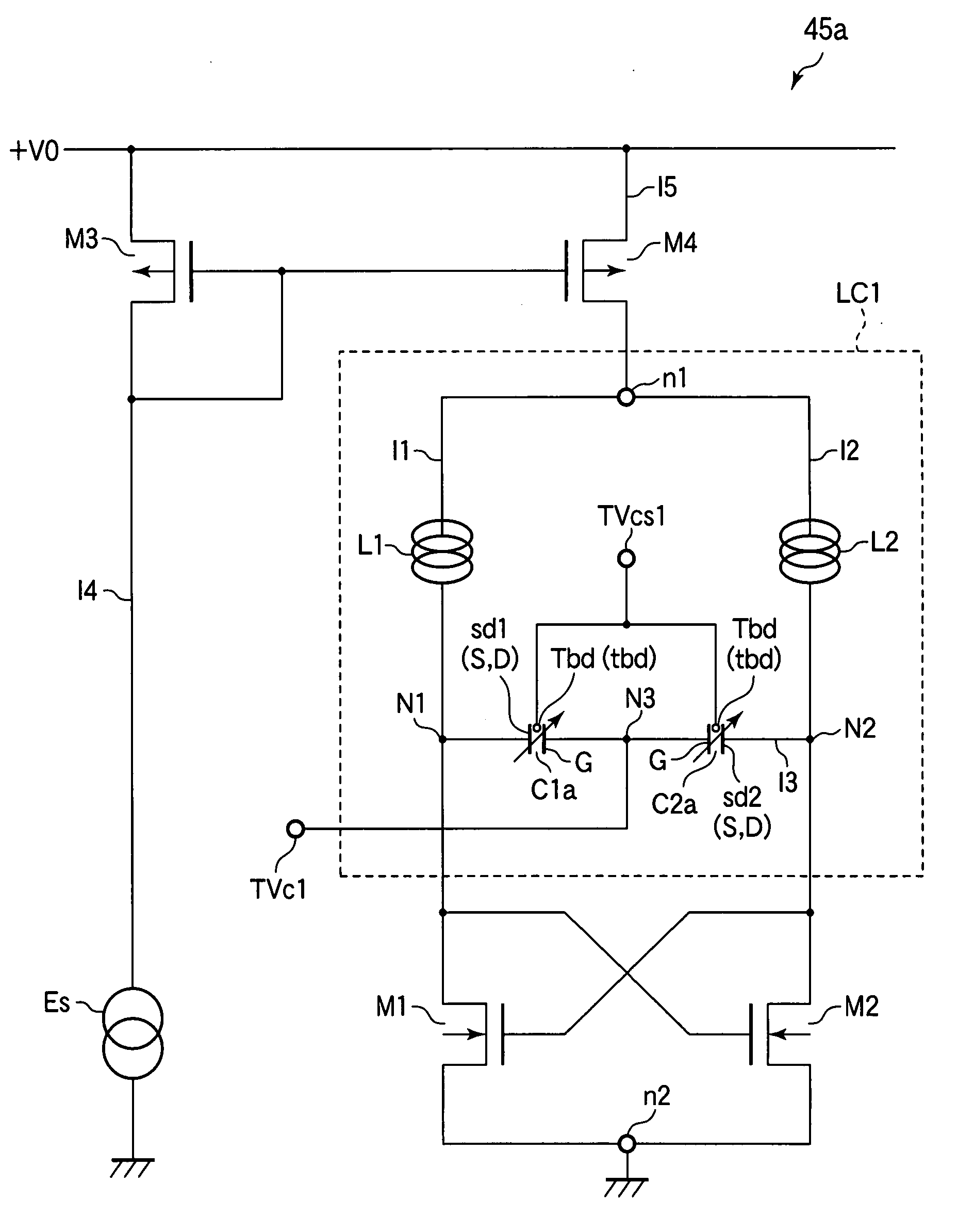
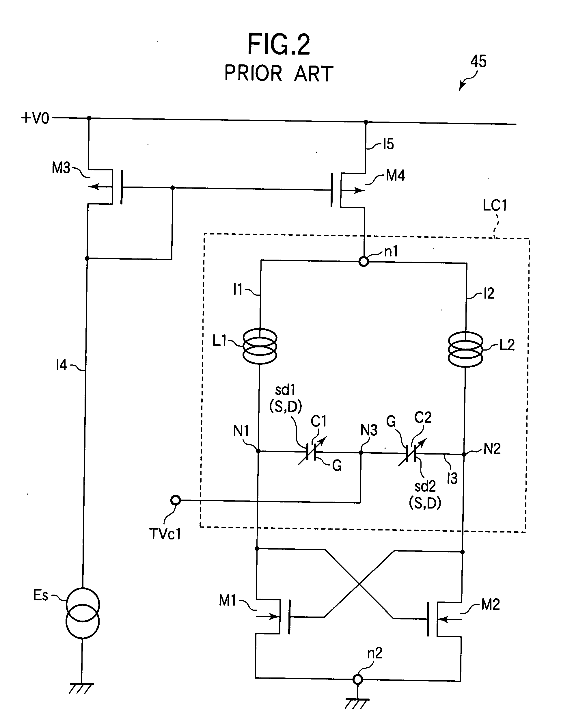
[0065]Referring to FIG. 8, the novel VCO 45a differs from the conventional VCO shown in FIG. 2 by using varactors C1a, C2a with body terminals Tbd connected to an adjustment voltage input terminal or control shifting voltage input terminal TVcs1. Like the conventional varactors, the varactors C1a, C2a with body terminals are capacitors with static capacitance values that can be controlled by a voltage signal applied to their gate electrodes G. The body terminals Tbd are disposed on one of the major surfaces of each capacitor (referred to below as the top s...


PUM


Abstract

A voltage controlled oscillator (VCO) conducts current on two paths through parallel inductors and parallel cross-coupled metal-oxide-semiconductor transistors. A pair of varactors are connected in series on a third path extending from a node between one inductor and one transistor to a node between the other inductor and the other transistor. The oscillation frequency is controlled by a voltage applied to a node between the two varactors on the third path. Each varactor is structured as a metal-oxide-semiconductor transistor with interconnected source and drain electrodes, a gate electrode, a body region below the gate electrode, and a body terminal region extending beyond the gate electrode. An adjustment voltage applied to the body terminal region shifts the voltage-capacitance curve of the varactor and the voltage-frequency curve of the VCO without changing the shapes of these curves, providing a simple way to adjust the VCO to meet application requirements.

Description

BACKGROUND OF THE INVENTION[0001]1. Field of the Invention[0002]The present invention relates to a voltage controlled oscillator (VCO) incorporated into a semiconductor integrated circuit to generate a high-frequency signal.[0003]2. Description of the Related Art[0004]Advances in complementary metal-oxide-semiconductor (CMOS) fabrication technology have made it possible to fabricate, on a single semiconductor chip, devices having a variety of structures that include both active elements such as transistors and diodes and passive elements such as resistors, inductors, and capacitors. A VCO is one of these types of devices. VCOs are used, for example, in phase locked loops (PLLs) to synthesize high-frequency signals for numerous applications in a wide variety of chips.[0005]FIG. 1 shows the basic PLL structure. The PLL 10 includes a phase comparator 30, a low pass filter (LPF) 40, and a VCO 45. The phase comparator 30 receives a reference signal fr from an input terminal and receives ...

Claims


Application Information

Patent Timeline
IPC IPC(8): H03B5/12
CPCH03B2200/0062H03B5/1228H03B5/1293H03B5/1253H03B5/1215
Inventor CHIBA, TADASHI
Owner LAPIS SEMICON CO LTD
Why Eureka
Try Eureka