High power solid-state lamp

Active Publication Date: 2008-01-10
CREELED INC
View PDF103 Cites 31 Cited by
  • Summary
  • Abstract
  • Description
  • Claims
  • Application Information

AI Technical Summary

Benefits of technology

[0009] One embodiment of an optical device according to the present invention comprises a solid state light source and a first heat sink positioned in thermal contact with the light source. Heat from the light source transmits into the first heat sink. The first heat sink at lea

Problems solved by technology

Historically, however, LEDs have lacked brightness comparable to incandescent, fluorescent or vapor-discharge lights and thus these older technologies have continued to occupy the field.
This level of heat dissipation can cause LEDs to operate at relatively high temperatures.
Higher operating temperatures cause the device quantum effic

Method used


Image

  • High power solid-state lamp
  • High power solid-state lamp
  • High power solid-state lamp

Examples


Example

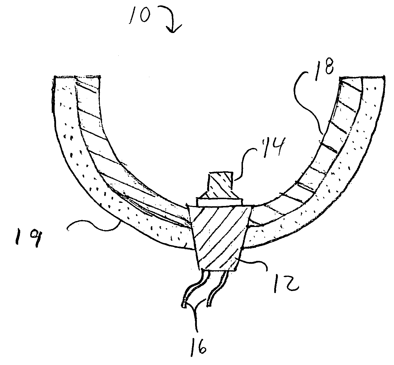
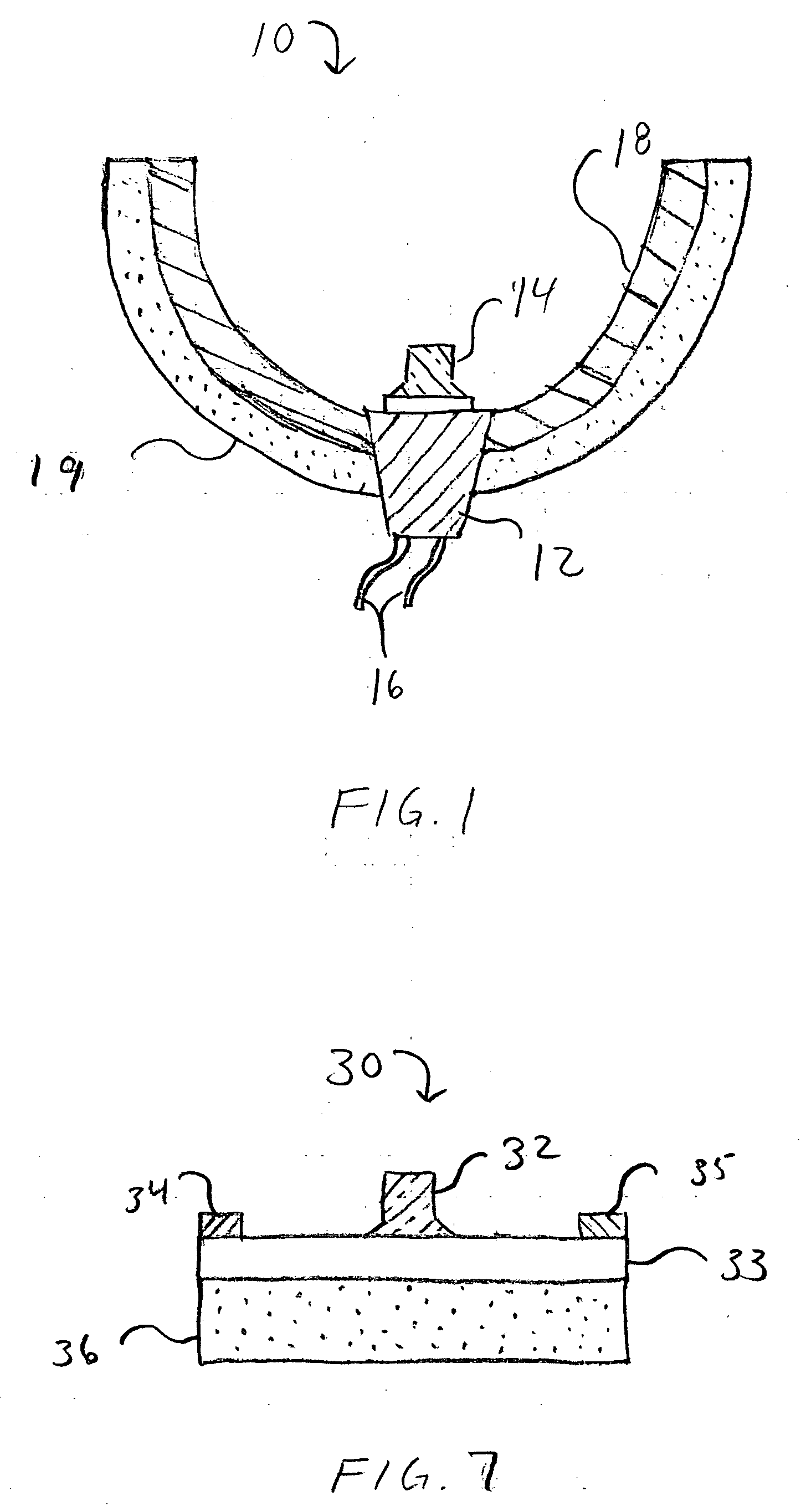
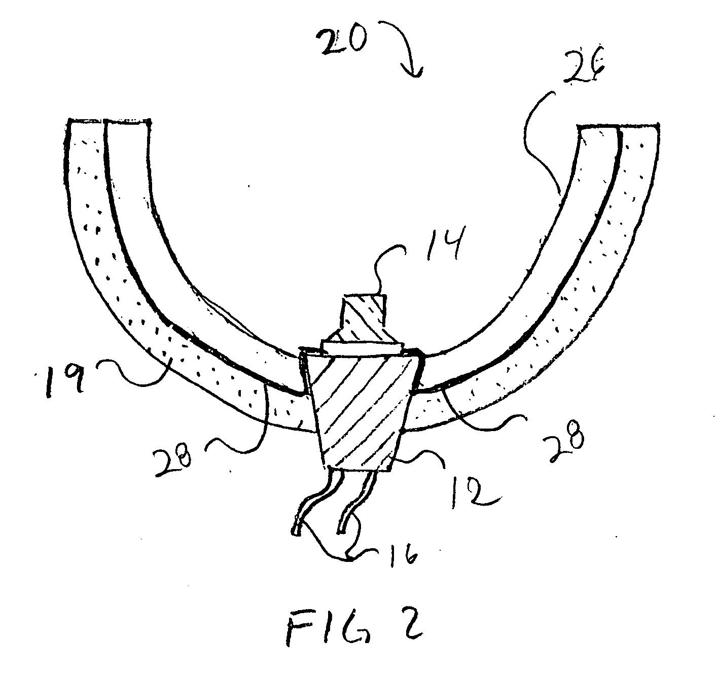
[0026] The present invention provides improved heat management for high-power solid state light emitters and power devices by utilizing one or more heat sinks that at least partially comprise porous structures made of high thermal conductivity material.

[0027] Many different types of porous material can be used including metals such as porous aluminum or copper, or inorganic materials such as carbon or porous ceramics. The pores in the material should interconnect to facilitate an effective convective heat exchange with the ambient, and the thickness of the material and pore size should provide for optimum conductive heat transfer through the pore structure without entrapping pockets of air within the material, and with the pores providing a continuous air channel to the ambient. The porous material should be arranged in thermal contact with the particular emitter or power device so that heat conducts from the device into and throughout the porous material (foam). The porous materia...


PUM


Abstract

A high power semiconductor component structure having a semiconductor device arranged to operate in response to an electrical signal, with the device heating up during operation in response to the electrical signal. A heat sink is positioned in thermal contact with the semiconductor device such that heat from the device transmits into the first heat sink. The heat sink has at least partially a porous material region of a thermally conductive material in a 3-dimensional pore structure with the surfaces of the pore structure providing surface area for heat to dissipate into the ambient air.

Description

BACKGROUND OF THE INVENTION [0001] 1. Field of the Invention [0002] This invention relates to high power semiconductor devices and more particularly, to improved heat sinks for heat management of high power semiconductor light emitters and power devices. [0003] 2. Description of the Related Art [0004] Light emitting diodes (LEDs) are an important class of solid-state devices that convert electric energy to light energy and generally comprise an active layer of semiconductor material sandwiched between two oppositely doped layers. When a bias is applied across the doped layers, holes and electrons are injected into the active layer where they recombine to generate photons and phonons. Photons are useful because they provide radiative recombination or light, which is typically emitted omnidirectionally from the active layer and from the surfaces of the LED. [0005] LEDs have the potential to provide replacement for long-standing illumination technologies such as incandescent and fluore...

Claims


Application Information

Patent Timeline
IPC IPC(8): F21V29/00H01L33/60H01L33/64
CPCH01L33/60H01L33/641H01L33/642H01L2924/0002H01L2924/00
Inventor KELLER, BERNDIBBETSON, JAMES
Owner CREELED INC
Why Eureka
Try Eureka