Power supply apparatus including charge-pump type step-up circuit having different discharging time constants

a technology of step-up circuit and power supply apparatus, which is applied in the direction of dc-dc conversion, power conversion systems, instruments, etc., can solve the problems of remarkably increasing power consumption, reduce response characteristics of comparators, and increase the ripple of step-up circuit output voltage.

Inactive Publication Date: 2008-01-10
RENESAS ELECTRONICS CORP
View PDF2 Cites 29 Cited by
  • Summary
  • Abstract
  • Description
  • Claims
  • Application Information

AI Technical Summary

Benefits of technology

[0007]In order to decrease the power consumption, the response characteristics of the comparator are decreased or the comparator is a hysteresis-type comparator, by which large overshoots would be generated, which would deteriorate the elements of the apparatus. Also, the ripple of the output voltage of the step-up circuit would be increased.

Problems solved by technology

In the above-described prior art power supply apparatus, however, when a driven load is relatively small and the response characteristics of the comparator are relatively high, the power consumption would be remarkably increased.

Method used


Image

  • Power supply apparatus including charge-pump type step-up circuit having different discharging time constants
  • Power supply apparatus including charge-pump type step-up circuit having different discharging time constants
  • Power supply apparatus including charge-pump type step-up circuit having different discharging time constants

Examples


Embodiment Construction

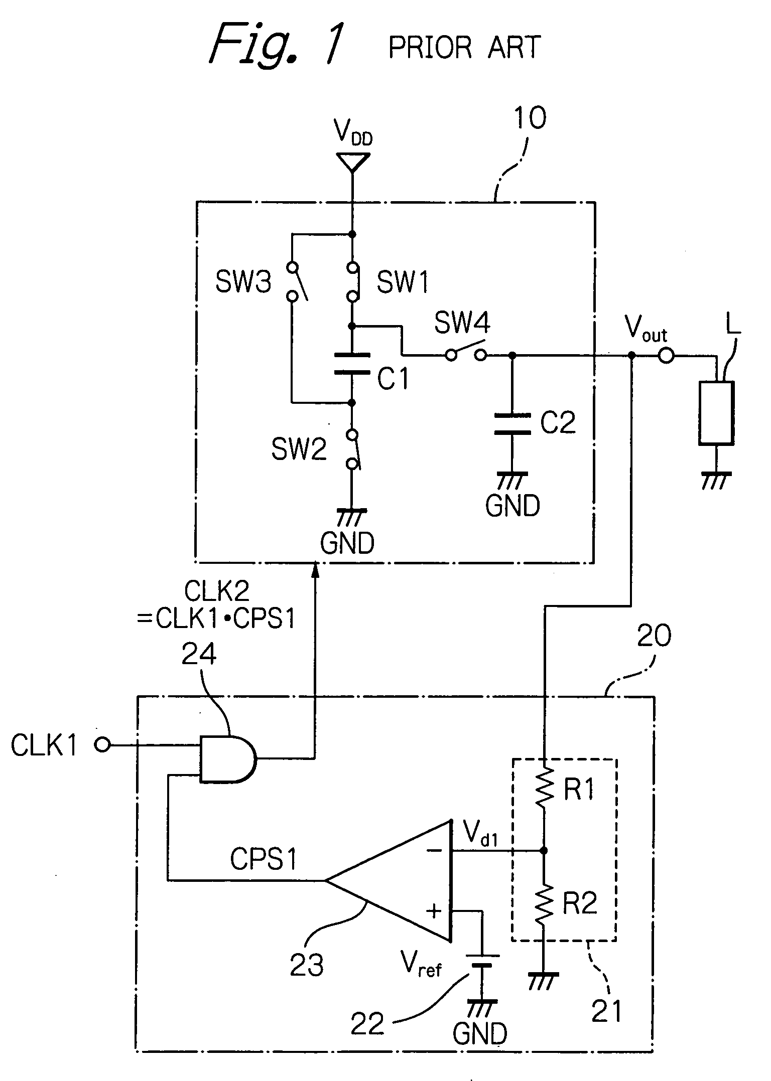
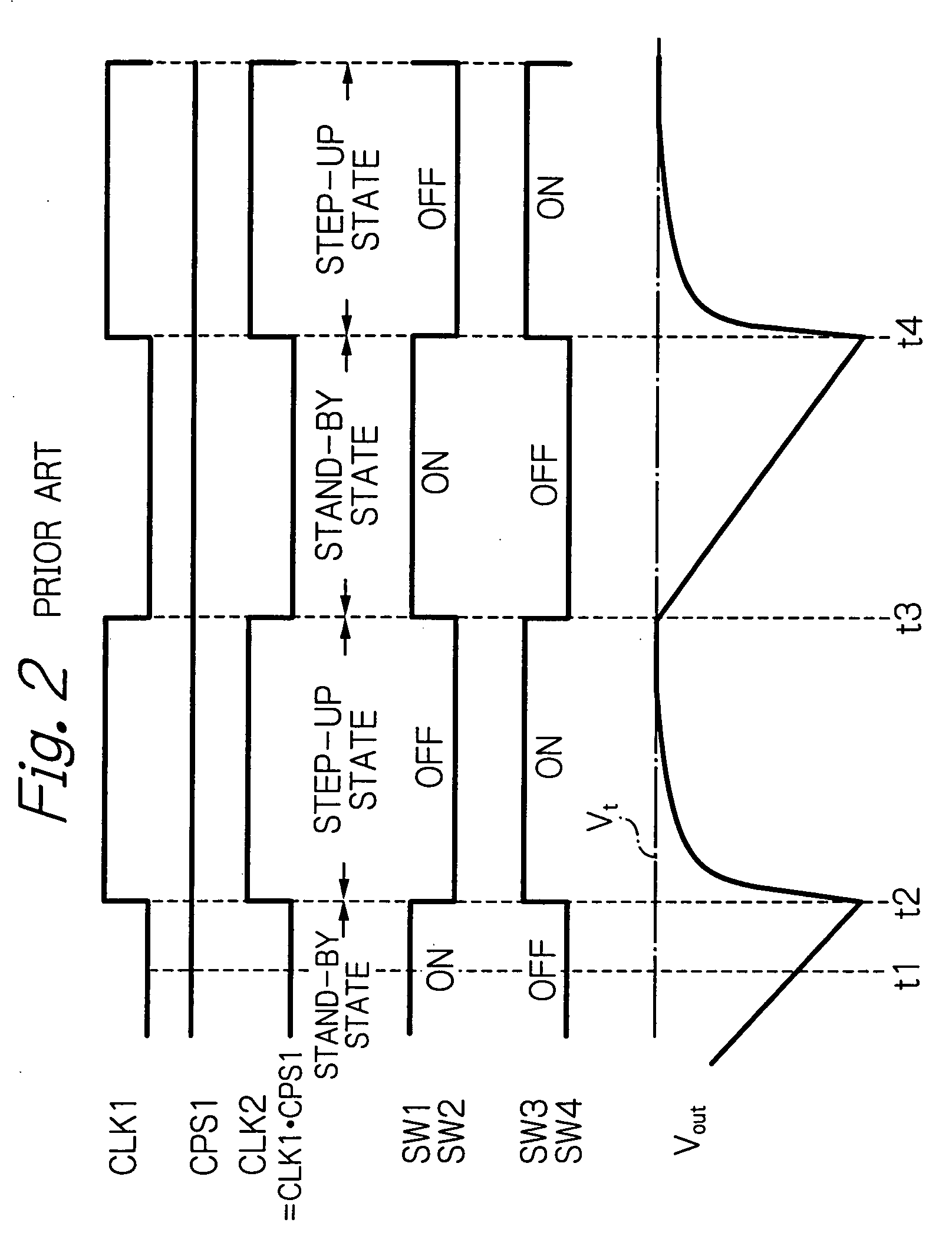
[0019]Before the description of the preferred embodiment, a prior art power supply apparatus will be explained with reference to FIGS. 1, 2, 3 and 4 (see: FIGS. 3, 4 and 5 of JP-2005-20971 A).

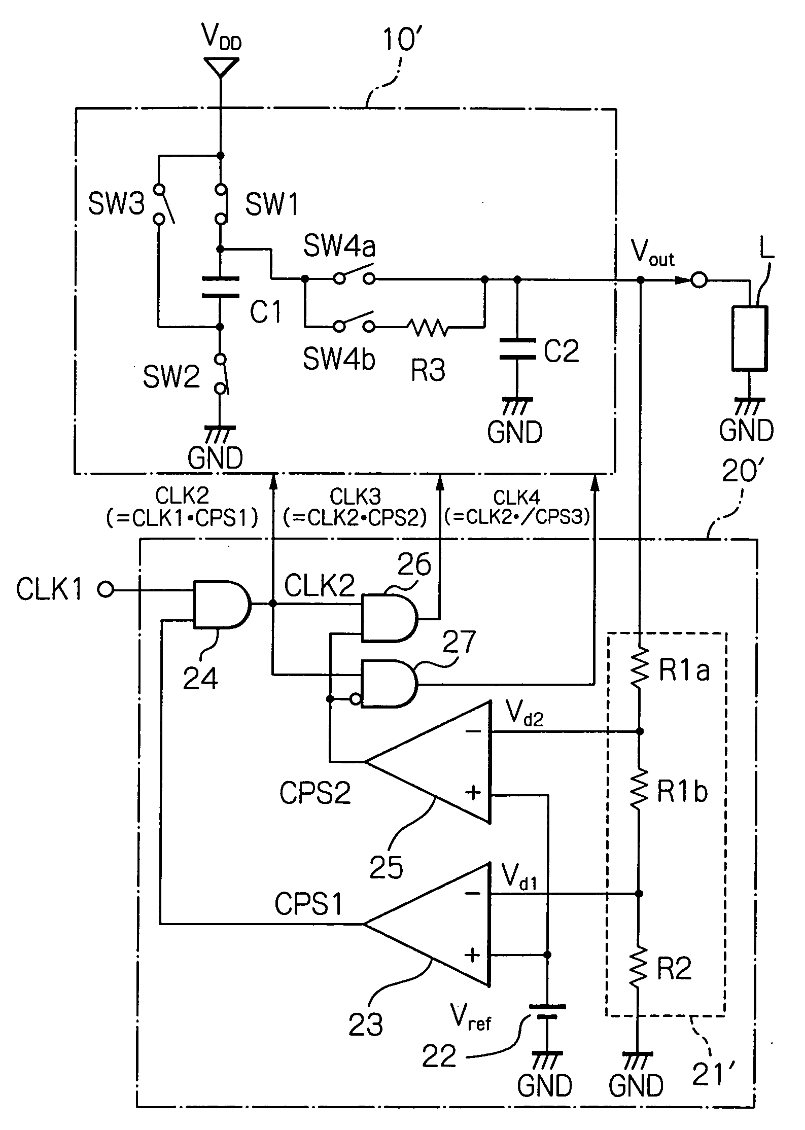
[0020]In FIG. 1, a prior art power supply apparatus is constructed by a step-up circuit 10 for stepping up a power supply voltage VDD as an input voltage in accordance with a skipped clock signal CLK2 of a clock signal CLK1 to generate a stepped-up voltage, i.e., an output voltage Vout, and a regulator 20 for regulating the output voltage Vout of the step-up circuit 10 to a target voltage Vt. In this case, the regulator 20 skips the clock signal CLK1 in accordance with the output voltage Vout of the step-up circuit 10 to generate the clock signal CLK2 and transmit it to the step-up circuit 10.

[0021]The charge pump circuit 10 is constructed by four switches SW1, SW2, SW3 and SW4, a step-up capacitor C1 and a smoothing capacitor C2. In this case, the set of the switches SW1 and SW2 as charging sw...


PUM


Abstract

In a power supply apparatus, a charge-pump type step-up circuit is adapted to charge a step-up capacitor by a power supply voltage, step up a charged voltage of the step-up capacitor using a charge-pump operation, and discharge a stepped-up voltage to a smoothing capacitor. A regulator has a first comparator adapted to compare a voltage corresponding to an output voltage of the step-up circuit with a reference voltage to generate a comparison output signal and skip a clock signal in accordance with the comparison output signal, so that the output voltage of the step-up circuit is brought close to a target voltage. Discharging of the smoothing capacitor is carried out through a resistor with a predetermined time constant when the output voltage of the step-up circuit is between the target voltage and a voltage lower than the target voltage by a predetermined value.

Description

BACKGROUND OF THE INVENTION[0001]1. Field of the Invention[0002]The present invention relates to a power supply apparatus including a charge-pump type step-up circuit and a regulator for regulating the output voltage of the charge-pump type step-up circuit.[0003]2. Description of the Related Art[0004]A typical power supply apparatus suitably used in a driver for driving a display panel such as a liquid crystal display (LCD) panel of a mobile phone or a personal digital assistant (PDA) includes a charge-pump type step-up circuit and a regulator for regulating the output voltage of the charge-pump type step-up circuit.[0005]A prior art power supply apparatus is constructed by a charge-pump type step-up circuit having a single discharging (step-up) time constant of a smoothing capacitor, and a regulator formed by a voltage divider for dividing the output voltage of the step-up circuit to generate a divided voltage, a comparator for comparing the divided voltage with a reference voltage...

Claims


Application Information

Patent Timeline
Patent Type & Authority Applications(United States)
IPC IPC(8): H02M3/18
CPCH02M3/07
Inventor FUJIWARA, HIROFUMI
Owner RENESAS ELECTRONICS CORP
Why Eureka
Try Eureka