Shape-Retaining Fiber Optic Cables Having Limited Bend Radius

a fiber optic cable and bend radius technology, applied in the field of interconnections, can solve the problems of increasing insertion loss, fiber optic cable damage, and careful handling of fiber optic cables, and achieve the effect of accepting the bend radius and facilitating deformation

Active Publication Date: 2008-01-10
TELESCENT
View PDF6 Cites 151 Cited by
  • Summary
  • Abstract
  • Description
  • Claims
  • Application Information

AI Technical Summary

Benefits of technology

[0007]In accordance with this invention, fiber optic cables are provided whose shape may be formed and retained while maintaining an acceptable bend radius. These features are produced by incorporating a compact compliant internal cable member into the cable structure. The compliant internal member consists not only of the fiber optic cable, but also ductile and non-ductile elements. The ductile element is advantageously a tube or a wire which readily deforms to retain a given shape and may be reshaped if desired. The non-ductile element, which resists sharp bending of the cable during shaping, comprises a substantially non-ductile elongated element disposed within the cable and configured to oppose excessively sharp bending radius along its length. Proper selection of the cross-sections and materials used in these elongated members produces a proper balance between shape retention and bending radius.

Problems solved by technology

A unique characteristic of fiber-based transmission media is that considerable care must be taken in handling fiber optic cables because of the potential to damage the internal glass optical fiber.
Unlike most electrical cables, which can be sharply bent or subjected to significant forces without impacting their performance characteristics, fiber optic cables are readily damaged under small shear forces and must maintain greater than a minimum bend radius.
Sharp bends result in increased insertion loss, stress birefringence and ultimately fiber failure.
In addition, the interface between the polished fiber optic connector and cable is susceptible to damage arising from the concentration of stress at the point the cable enters the connector body.
The preparation of fiber optic patchcords requires the use of a polishing process which adds cost relative to electronic cabling.
Optical fiber cables can not be readily cut to length in the field, nor can they be folded to take up excess length.
Optical connectors are also highly susceptible to contamination or scratching.
This damage results in potential data corruption or complete loss of data transmission.
Such tension members are typically braided wire, which do not have appropriate mechanical characteristics to enable the cable to retain a shape.
However, this approach does not provide a means of limiting the bend radius in the bent state.
These factors make such a cable impractical for most applications, which require a solution that satisfies multiple requirements including low cost, light weight and small form factor.

Method used


Image

  • Shape-Retaining Fiber Optic Cables Having Limited Bend Radius
  • Shape-Retaining Fiber Optic Cables Having Limited Bend Radius
  • Shape-Retaining Fiber Optic Cables Having Limited Bend Radius

Examples


example

Materials

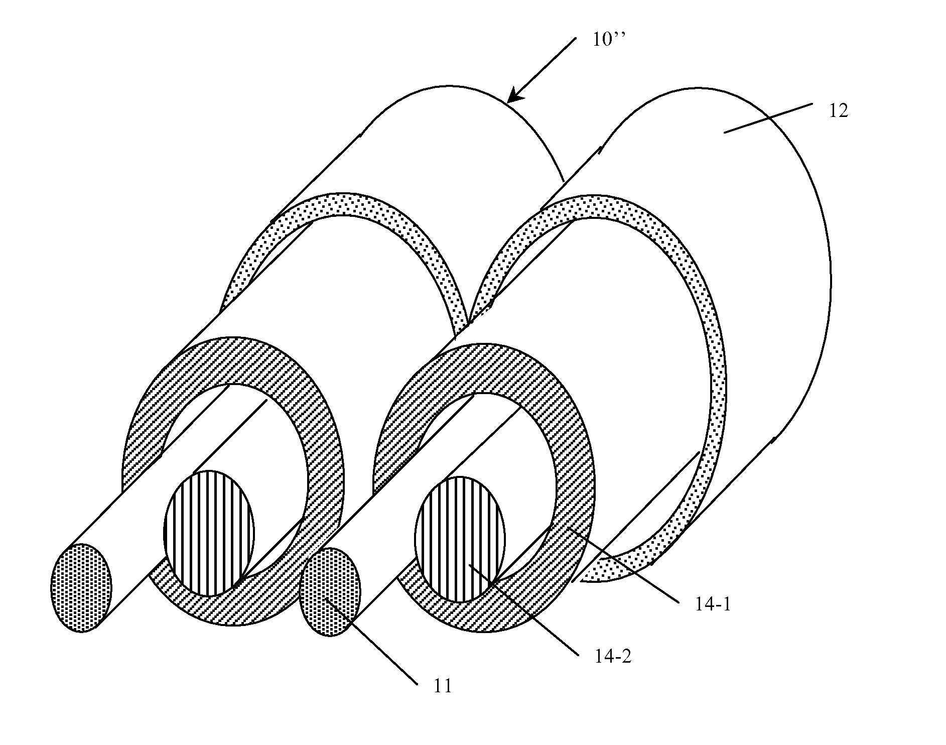
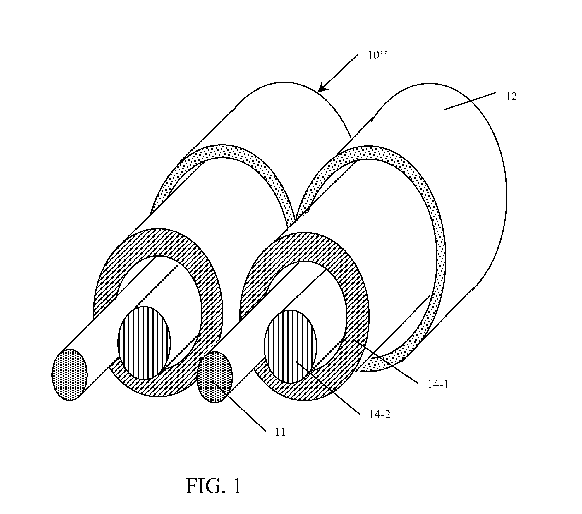
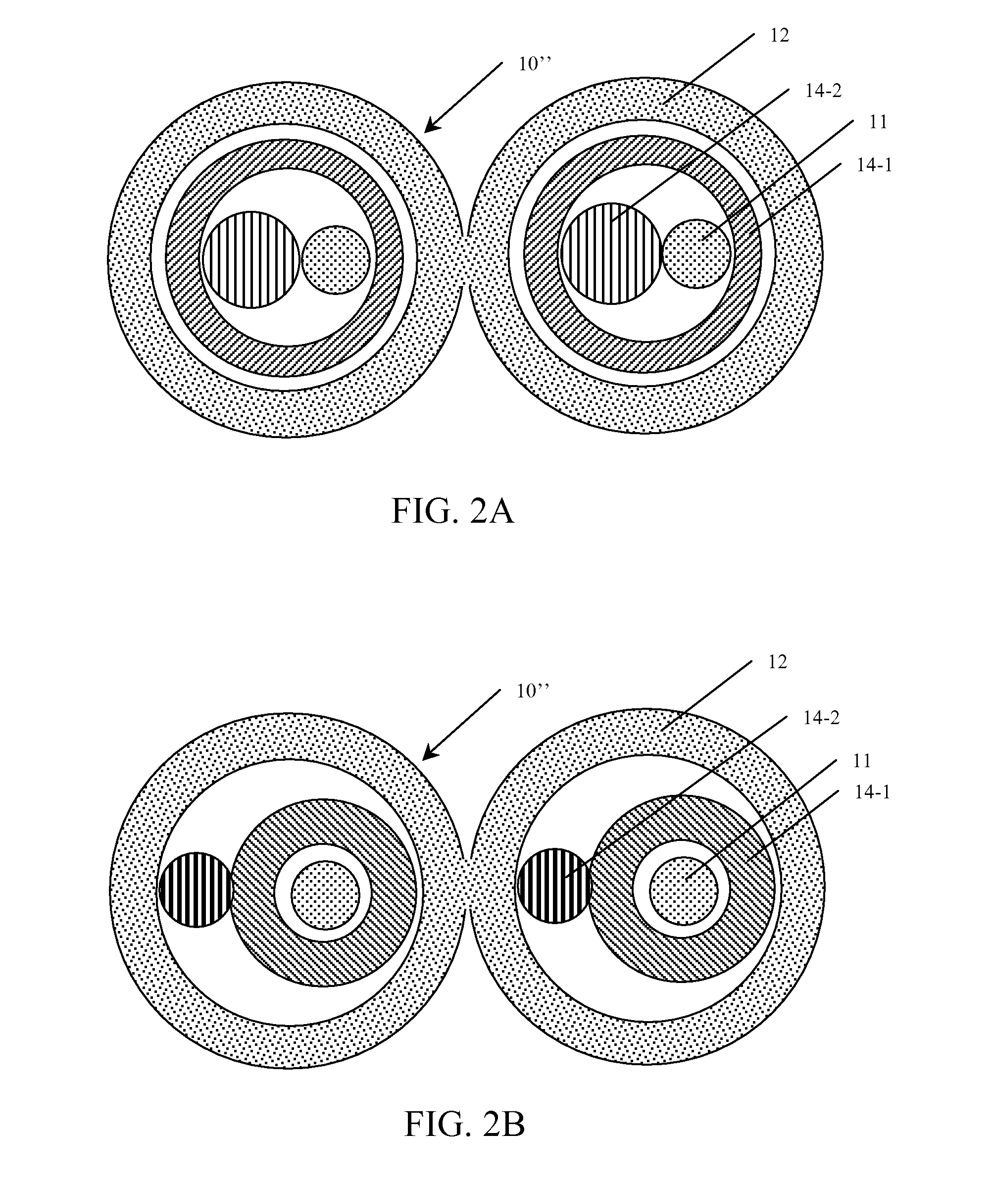
[0046]Suitable materials for use as the ductile element include, but are not limited to, the class of malleable metals which are highly ductile and relatively immune to work-hardening. Excessive work-hardening would potentially cause brittleness of the compliant material and lead to cracking and embrittlement over many cycles of cable shaping and reshaping. Optimal materials include soft annealed copper, brass, tin, aluminum or related alloys. In a particular example, the ductile element is comprised of soft annealed copper with 35,000 psi ultimate strength and 10,000 psi yield strength. In alternate examples, C260 (cartridge) brass with 47,900 psi ultimate strength and 16,000 psi yield strength or 1006-1008 series soft annealed steel may be utilized.

[0047]Materials suitable for the non-ductile element include, but are not limited to, the class of high strength, high carbon steel alloys. In a particular example, the non-compliant element is comprised of 1075-1095 series car...


PUM


Abstract

In accordance with this invention, fiber optic cables are provided whose shape may be formed and retained while maintaining a limited bend radius. These features are produced by incorporating a compact compliant internal cable member into the cable structure. The compliant internal member consists not only of the fiber optic cable, but also of ductile and non-ductile elements. The ductile element is advantageously a tube or a wire which readily deforms to retain a given shape, and may be reshaped if desired. The non-ductile element, which resists sharp bending of the cable during shaping, comprises a substantially non-ductile elongated element disposed within the cable and configured to oppose excessively sharp bending along its length. Proper selection of the cross-sections and materials used in these elongated members produces a proper balance between shape retention and bending radius.

Description

REFERENCE TO RELATED APPLICATIONS[0001]This disclosure claims priority on U.S. Provisional Application No. 60 / 819,306 entitled “Shape-Retaining Fiber Optic Cables Using a Compliant Insert” by A. Kewitsch and filed on Jul. 6, 2006.FIELD OF THE INVENTION[0002]This invention relates to interconnects using fiber optic cables to transmit illumination and / or signals, and more particularly to shape-retaining and bend radius limited fiber optic patch cords.BACKGROUND OF THE INVENTION[0003]The development of improved techniques to interconnect and deliver optical power and signals in optical fiber systems is of growing importance as optical fiber technologies spread to various telecommunications, networking, industrial and medical applications. A unique characteristic of fiber-based transmission media is that considerable care must be taken in handling fiber optic cables because of the potential to damage the internal glass optical fiber. Unlike most electrical cables, which can be sharply b...

Claims


Application Information

Patent Timeline
Patent Type & Authority Applications(United States)
IPC IPC(8): G02B6/44
CPCG02B6/4478
Inventor KEWITSCH, ANTHONY STEPHEN
Owner TELESCENT
Why Eureka
Try Eureka