Rotating electrical machine

a technology of rotating electrical machines and rotating parts, which is applied in the direction of rotating magnets, synchronous machines with stationary armatures, magnetic circuit rotating parts, etc., can solve the problems of increasing the inside area of the hysteresis curve, complex core shape, and decreasing magnetic properties, so as to reduce iron loss

Inactive Publication Date: 2008-01-17
HITACHI LTD
View PDF9 Cites 28 Cited by
  • Summary
  • Abstract
  • Description
  • Claims
  • Application Information

AI Technical Summary

Benefits of technology

[0026]According to the present invention, it is possible to provide a rotating electrical machine which can reduce iron loss.

Problems solved by technology

Furthermore, the stator core has a complicated shape having teeth and slots, and in the current circumstances, stator cores are made by a punching method.
Punching deforms the crystalline structure of the cut section of the electromagnetic steel sheet, which decreases magnetic property and increase the area of the inside of the hysteresis curve, thereby increasing iron loss.
As a result, there is a problem in that efficiency in a rotating electrical machine cannot be improved.

Method used


Image

  • Rotating electrical machine
  • Rotating electrical machine
  • Rotating electrical machine

Examples


Embodiment Construction

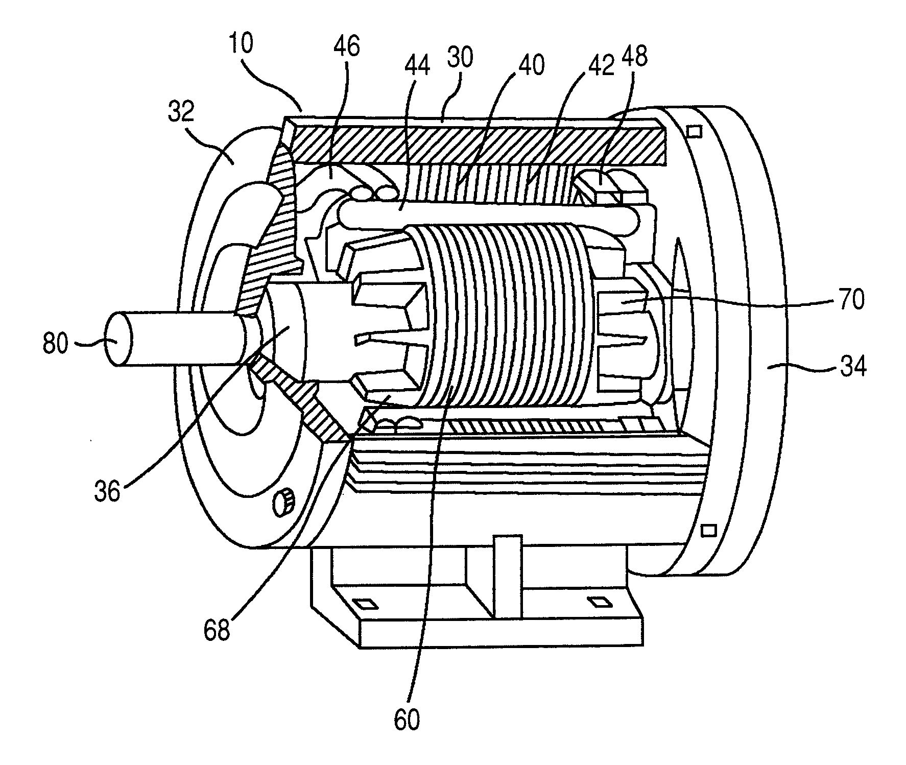
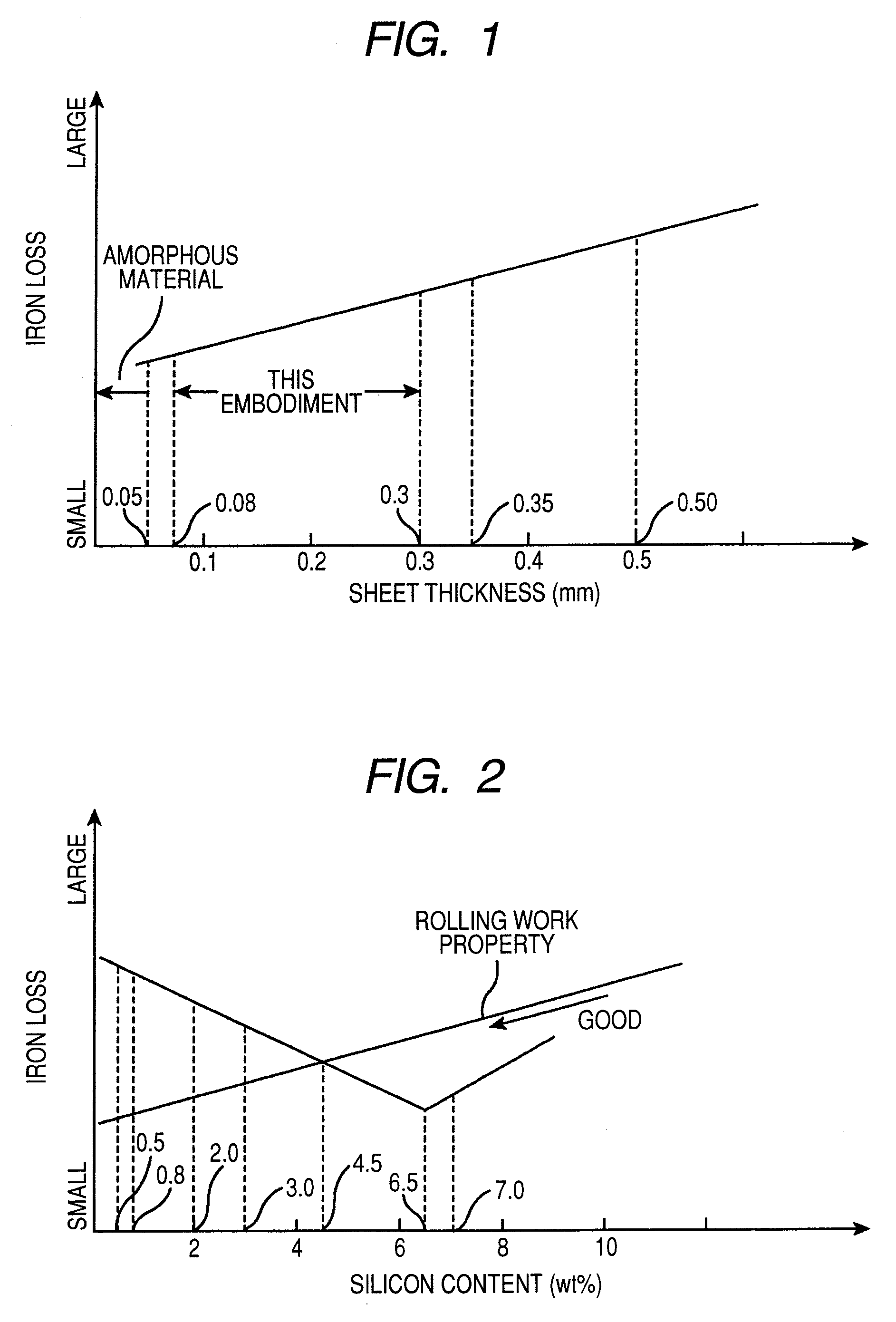
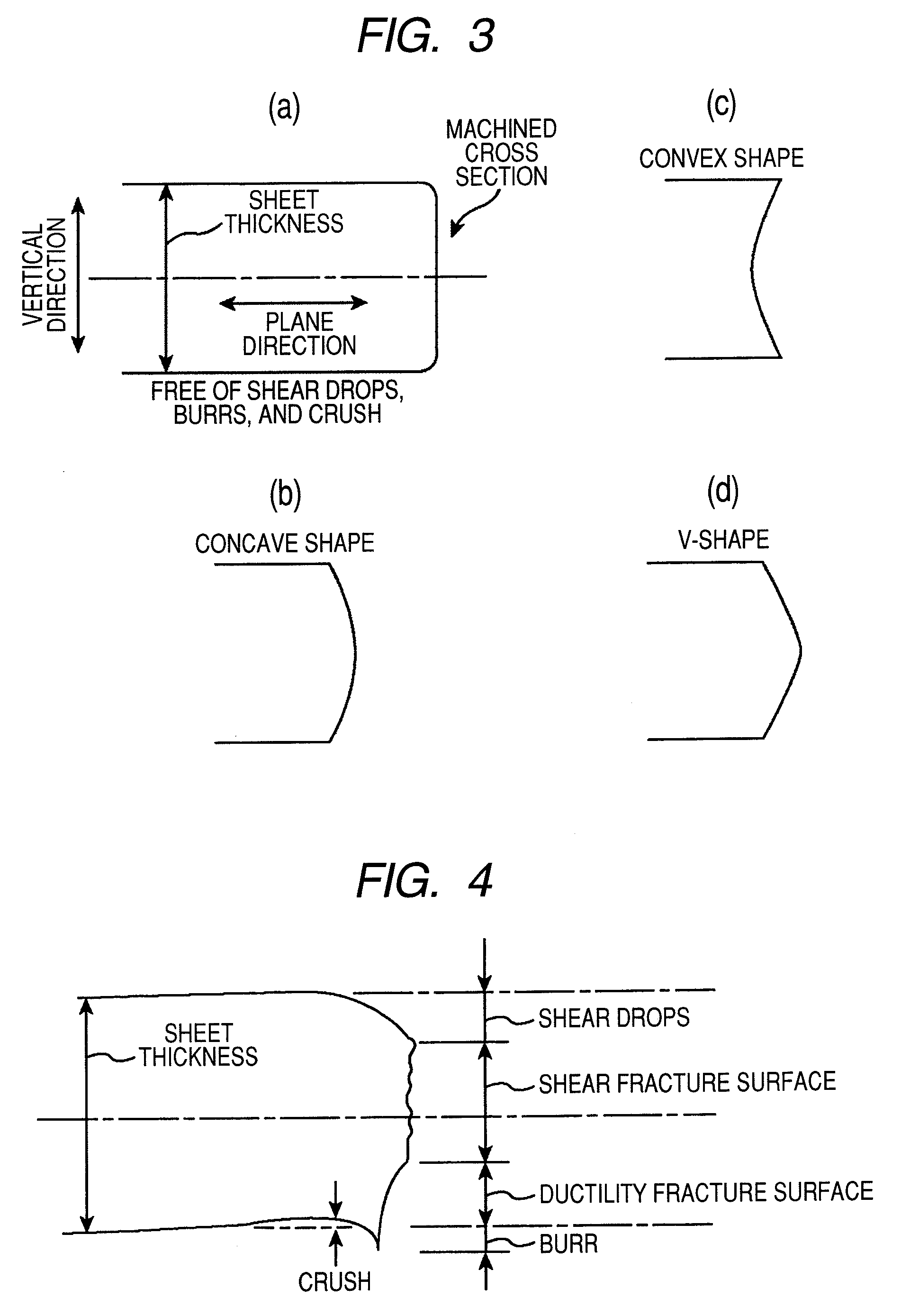
[0040]One of two rotating electrical machines described in this embodiment is an induction motor and the other is a synchronous motor equipped with a permanent magnet. Each of the two motors has a stator and a rotor, and the stator comprises a stator core, having teeth and slots, and stator windings disposed in the slots. The stator core (hereafter sometimes referred to as “core”) is made of laminated steel sheets, and the steel sheet's teeth and slots are made by etching, preferably by photo-etching. Herein, the thickness of the steel sheet is between 0.08 mm and 0.30 mm.

[0041]Of course, it is desirable that the entire stator core be etched from the viewpoint of improving magnetic property and the workability of the entire production process.

[0042]Furthermore, with regard to a rotor core, in the same manner as a stator core, it is desirable that a silicon steel sheet having thickness between 0.08 mm and 0.30 mm be etched from the viewpoint of the improvement of magnetic property. T...


PUM

PropertyMeasurementUnit
thicknessaaaaaaaaaa
thicknessaaaaaaaaaa
thicknessaaaaaaaaaa

Abstract

A rotating electrical machine comprises a stator and a rotor; the stator comprising a stator core having teeth and slots, and stator windings disposed in the slots, wherein the stator core is made of laminated steel sheets, teeth and slots of the steel sheet are made by etching, and the thickness of the steel sheet is between 0.05 mm and 0.30 mm. Specifically, it is preferable that the steel sheet used herein be a silicon steel sheet containing crystalline particles.

Description

CLAIM OF PRIORITY[0001]The present application claims priority from Japanese application serial no. 2006-192286, filed on Jul. 13, 2006, the content of which is hereby incorporated by reference into this application.FIELD OF THE INVENTION[0002]The present invention relates to a rotating electrical machine which uses laminated electromagnetic steel sheets.BACKGROUND OF THE INVENTION[0003]A rotating electric motor is one example of a rotating electrical machine. The efficiency in a rotating electric motor has improved significantly because a synchronous electric motor having a rotor equipped with a permanent magnet is used.[0004]However, it is desirable that the efficiency be further improved. A cause of decreased efficiency in a rotating electrical machine is iron loss in the stator core of the stator used in a rotating electrical machine. It is desirable that the iron loss should be reduced to provide a rotating electrical machine which is highly efficient.[0005]For example, techniq...

Claims


Application Information

Patent Timeline
Patent Type & Authority Applications(United States)
IPC IPC(8): H02K1/12H02K1/27
CPCH02K1/06H02K15/024H02K1/276H02K1/16
Inventor ABE, TERUYOSHIITO, MOTOYATAJIMA, FUMIOISHIKAWA, YOSHIHISA
Owner HITACHI LTD
Why Eureka
Try Eureka