Supercharge Your Innovation With Domain-Expert AI Agents!

Electric discharge lamp

Inactive Publication Date: 2008-01-17
NEC LIGHTING
View PDF4 Cites 0 Cited by
  • Summary
  • Abstract
  • Description
  • Claims
  • Application Information

AI Technical Summary

Benefits of technology

[0011]The present invention aims at providing an electric discharge lamp which can reduce dispersion in operating temperature of a thermal fuse at the time that emissive material of an electrode is exhausted and at the time an anomalous discharge is caused, and can stop supply of a current before the temperature of a part of a glass tube becomes relatively high.
[0014]An exemplary advantage according to the present invention is that, it is possible to reduce dispersion in operating temperature of a thermal fuse at the time when an anomalous discharge occurs, and to stop supply of a current before temperature of a part of a glass tube becomes relatively high.

Problems solved by technology

In this kind of hot cathode electric discharge lamp, since anomalous discharge is caused after an emissive material (emitter) is dispersed at end of life, a preheating current increases, or an electrode material, a lead wire material, or the like disperses and adheres on a surface of a stem, which supports lead wires because of insufficient discharge.
For this reason, the electric discharge lamp generates heat by a short circuit arising between lead wires and a preheating current flowing on the surface of the stem, and has a possibility of melting the glass material, which makes up the stem, and the glass tube.
For this reason, there is an issue that dispersion of temperature which the thermal fuse detects becomes large according to the installation position of the thermal fuse.
Hence, the construction of this patent publication only discloses a possibility that the dispersion in operating temperature of the thermal fuse may become large because of the position where the thermal fuse is arranged.
Such a construction is inconvenient in that dispersion in the operating temperature of a thermal fuse adversely affect a member which is used to construct a liquid crystal display even if the stem does not reach melting point.

Method used


Image

  • Electric discharge lamp
  • Electric discharge lamp
  • Electric discharge lamp

Examples


Embodiment Construction

[0017]Hereafter, specific exemplary embodiments will be described with reference to drawings.

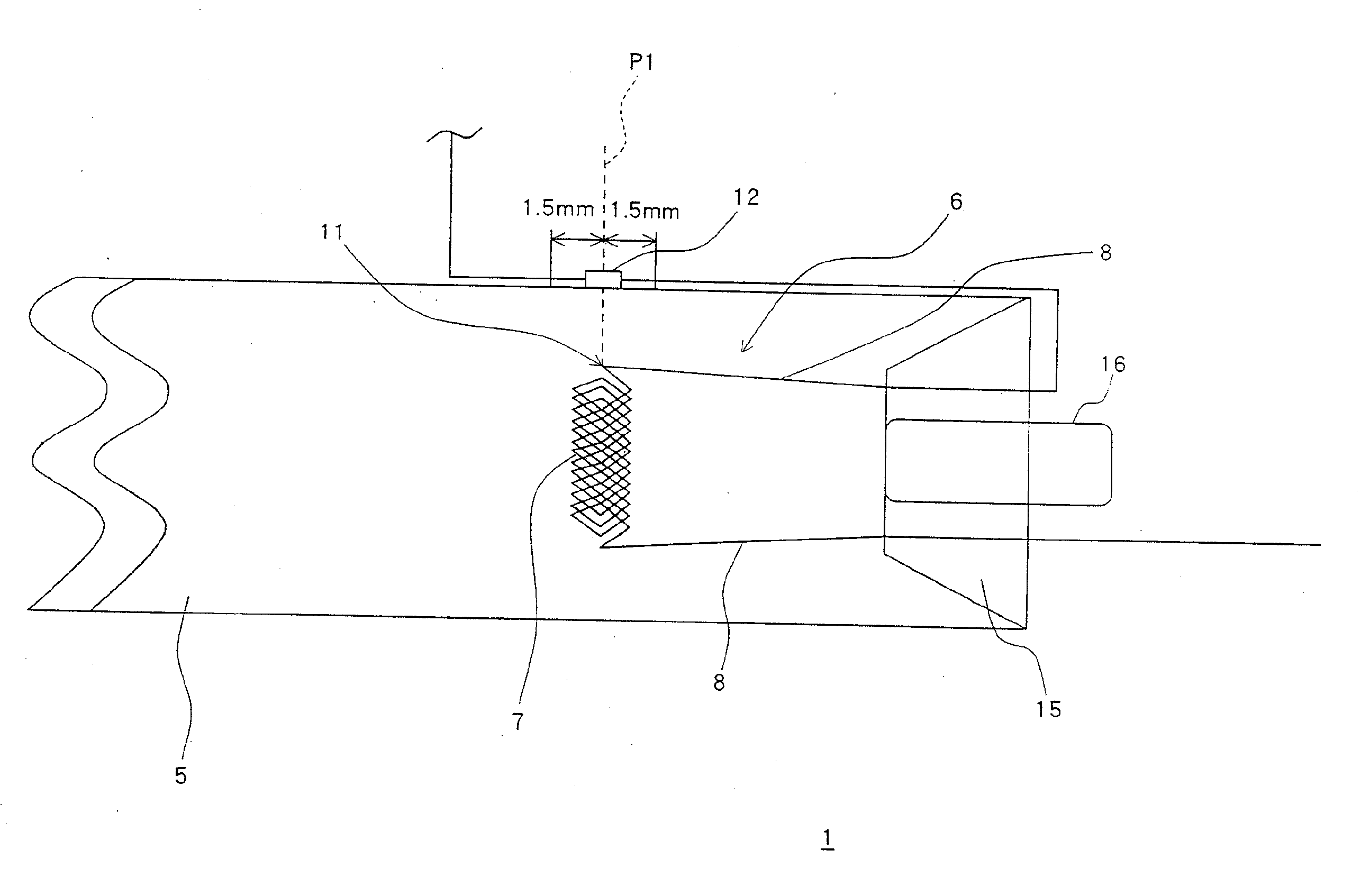
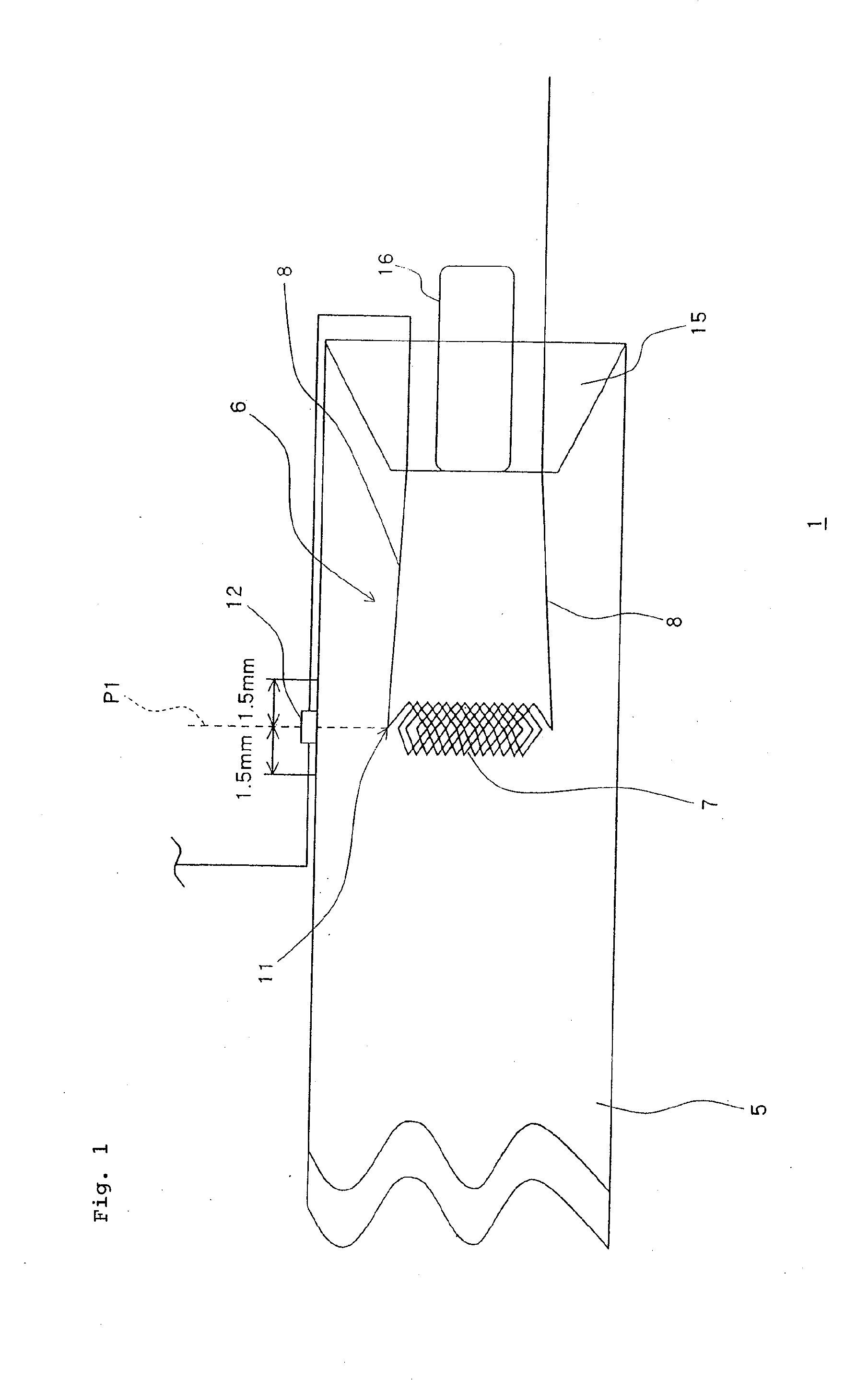
[0018]As illustrated in FIG. 1, fluorescent lamp 1 as an electric discharge lamp includes electrode 6, and cylindrical glass tube 5 which has electrodes 6 at each end inside the glass tube.

[0019]Electrode 6 has filament 7 with the end of each lead wires 8 connected to each end of the filament. The other ends of lead wires 8 of electrode 6 are supported by stem 15 formed in an end portion of glass tube 5. In addition, exhaust pipe 16 communicating inside glass tube 5 is provided in stem 15.

[0020]In addition, on an outer peripheral surface of glass tube 5, thermal fuse 12 is provided near electrode 6. This thermal fuse 12 is electrically connected to lead wires 8 in series.

[0021]Then, when a position on the outer peripheral surface of glass tube 5, which extends in a radial direction of glass tube 5 from a connecting portion 11 of filament 7 and lead wire 8, serves as a reference position P1, ...


PUM


Abstract

The present invention includes an electrode having a filament with the end of each lead wire connected to each end of the filament, a cylindrical glass tube in which the electrode is provided, and a thermal fuse which is electrically connected to the lead wires in series, and is provided near the electrode on an outer peripheral surface of the glass tube, wherein, when a position on the outer peripheral surface of the glass tube which extends in a radial direction of the glass tube from a connecting portion of the filament and the lead wire, serve as a reference position, in case where the diameter of the glass tube is 8 mm or more, the thermal fuse is arranged at a distance of 1.5 mm or less from the reference position in the longitudinal direction of the glass tube.

Description

[0001]This application is based upon and claims the benefit of priority from Japanese patent application No. 2006-191980, filed on Jul. 12, 2006, the disclosure of which is incorporated herein in its entirety by reference.BACKGROUND OF THE INVENTION[0002]1. Field of the Invention[0003]The present invention relates to an electric discharge lamp, such as a fluorescent lamp, having an electrode with a filament and lead wires connected thereto.[0004]2. Description of the Related Art[0005]Generally, a hot cathode electric discharge lamp includes an electrode and a cylindrical glass tube which has electrodes at each end inside the glass tube. An electric discharge lamp, comprising an electrode having a filament with the end of each lead wire connected to each end of the filament. The other ends of the lead wires of the electrode are supported by a stem formed in an end portion of the glass tube.[0006]In this kind of hot cathode electric discharge lamp, since anomalous discharge is caused ...

Claims


Application Information

Patent Timeline
IPC IPC(8): H01K5/02
CPCG02F2001/133612H01J61/72H01J61/56G02F1/133612H01J7/44
Inventor HASHIMOTO, MASAFUMI
Owner NEC LIGHTING
Features
  • R&D
  • Intellectual Property
  • Life Sciences
  • Materials
  • Tech Scout
  • Unparalleled Data Quality
  • Higher Quality Content
  • 60% Fewer Hallucinations
Learn More