Movable Pin Ultrasonic Transducer

Inactive Publication Date: 2008-01-17
FEINE JAMES MR
View PDF13 Cites 34 Cited by
  • Summary
  • Abstract
  • Description
  • Claims
  • Application Information

AI Technical Summary

Benefits of technology

[0007] The present invention solves the problems inherent in the prior art by allowing precision electromagnetic ultrasonic tools to be developed with the following advantages: (1) higher precision frequency control than available in the prior

Problems solved by technology

Each of these methods has one or more disadvantages: heat buildup, power-control, high voltage requirement, fragility, limited or fixed frequency,

Method used


Image

  • Movable Pin Ultrasonic Transducer
  • Movable Pin Ultrasonic Transducer
  • Movable Pin Ultrasonic Transducer

Examples


Example

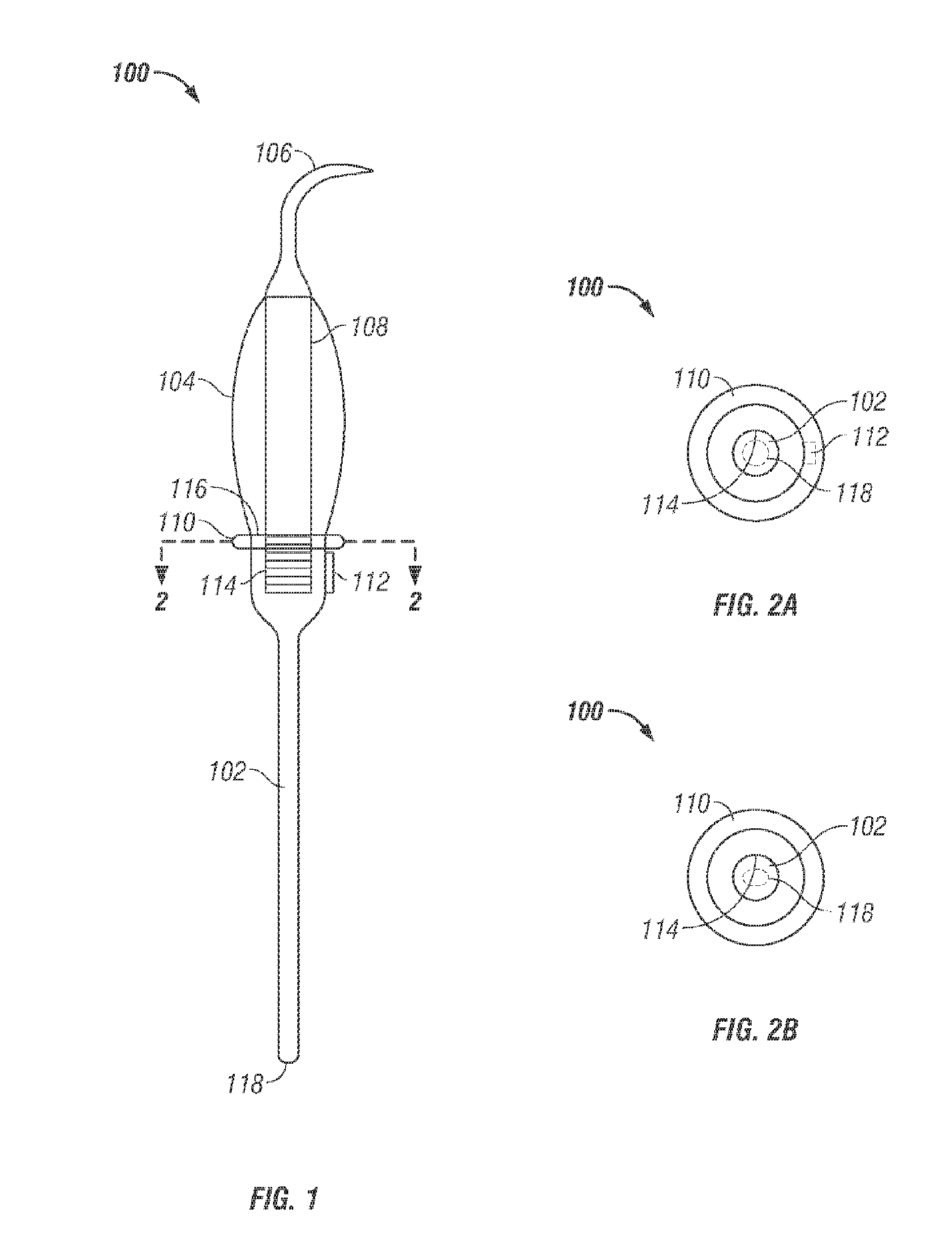
[0042] With reference to the figures wherein like reference numerals are used to refer to like parts, FIG. 1 shows a moveable pin transducer (MPT) 100 of an ultrasonic tool, according to one embodiment of the invention. The MPT 100 includes a magnetic rod 102 and a tip 106. Tip 106 can be a dental or surgical tip as is know in the art. The tip 106 is generally manufactured from a tubing piece of the appropriate inside and outside diameters which is bent and molded into the desired shape and then hardened and polished. A stainless steel, such as 420 or 440 grade, is generally suitable for this purpose, but, depending on the function or purpose of the tip 106, it can also be made from titanium or other materials, and can optionally be coated with an abrasive material such as diamond. The tip 106 can be a universal tip, a left tip or a right tip, have flattened sides and a spooned end, or can be a surgical blade, or any other element suitable for ultrasonic use. The tip can have an ape...


PUM


Abstract

An ultrasonic tool is disclosed with a handpiece (300, 500, 806) containing coils (304A-304D; 504A-504D; 804A-804B) that produce an electromagnetic field that vibrates a magnetic rod (102, 702A, 702B, 820) of a moveable pin transducer (MPT) 100 disposed within the handpiece. Ultrasonic vibrations are produced when the coils are selectively powered by an ultrasonic signal generator, which can include a stepper motor control apparatus (1300, 1400). A tip 106 can be removably attached to an MPT 100. A channel (708A, 708B) in the magnetic rod (700A, 700B) can allow fluidic communication with a handpiece fluid supply channel (310, 510). A method of vibrating a tool can include controllably energizing at least one electromagnetic coil contained within a handpiece to vibrate a magnetic rod and an attached tip. The method can include varying the energy to at least one of the electromagnetic coils with a stepper motor control apparatus.

Description

CROSS REFERENCE TO RELATED APPLICATION [0001] This application claims the benefit of my earlier application U.S. Ser. No. 60 / 595,867 filed Aug. 11, 2005.BACKGROUND [0002] This invention concerns the generation and utilization of ultrasonic energy as it applies to ultrasonic tools; specifically to an ultrasonic tool providing a tip connected to a movable magnetic rod vibrated by closely positioned electromagnetic coils in a handpiece. [0003] In the past, ultrasonic energy for applications, for example, dental scaling, was generated by use of magnetostrictive, piezoelectric, ferritestrictive, or air driven elements. Each of these methods has one or more disadvantages: heat buildup, power-control, high voltage requirement, fragility, limited or fixed frequency, limited or fixed type of motion generated, or production expense. These disadvantages can limit the devices from performing their intended purposes. [0004] In contrast, an electromagnet is a well known device in which magnetism ...

Claims


Application Information

Patent Timeline
IPC IPC(8): A61B17/00
CPCA61C17/20A61B17/320068
Inventor FEINE, JAMES
Owner FEINE JAMES MR
Why Eureka
Try Eureka