Heat wick for skin cooling

a skin cooling and heat wick technology, applied in the field of support surfaces, can solve the problems of pressure ulcers, serious problems in bedridden or wheelchair-bound people, and the vast majority of caregivers in the setting being unable to use them

Inactive Publication Date: 2008-01-17
LACHENBRUCH CHARLES ARTHUR
View PDF9 Cites 33 Cited by
  • Summary
  • Abstract
  • Description
  • Claims
  • Application Information

AI Technical Summary

Benefits of technology

[0014] The “heat wick” of the present invention provides steady-state cooling of the skin generally without requiring external power or circulation of air. In a non-powered surface according to the invention, the skin is cooled passively by conduction (not convection) without external power. Heat may be withdrawn from the device using a thermoelectric module or other comp

Problems solved by technology

Bedsores, or decubitus ulcers, can be a serious problem in bedridden or wheelchair-bound patients, particularly for people who are paralyzed, emaciated, post-surgical, elderly, or diabetic.
With the serious infections that often ensue, pressure ulcers can become life-threatening.
It is clear that while new treatment solutions may be relatively effective, their cost precludes their use by the vast majority of caregivers in the settings in which pressure ulcers and other chronic wounds must be managed.
If nutrient deficit exceeds tissue demand over a given interval, the tissue wi

Method used


Image

  • Heat wick for skin cooling
  • Heat wick for skin cooling
  • Heat wick for skin cooling

Examples


Embodiment Construction

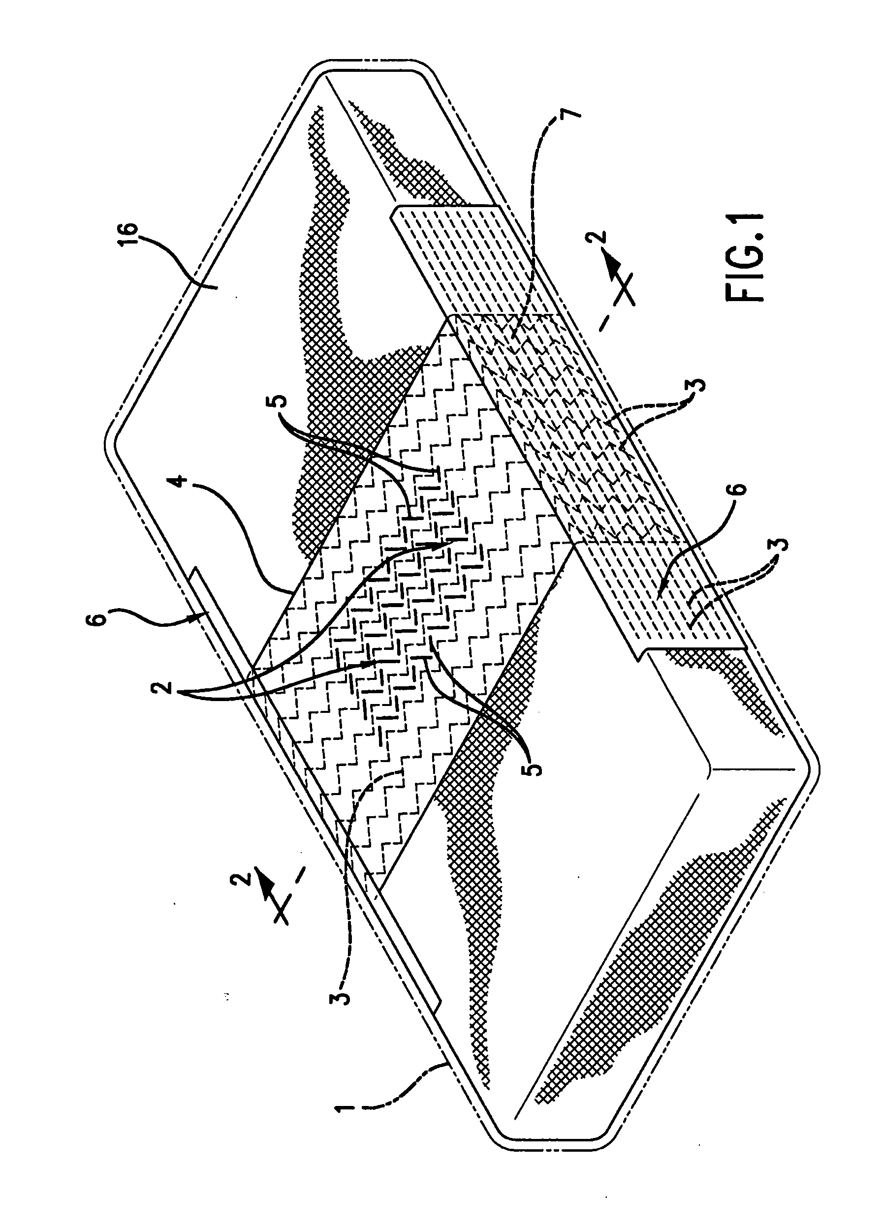
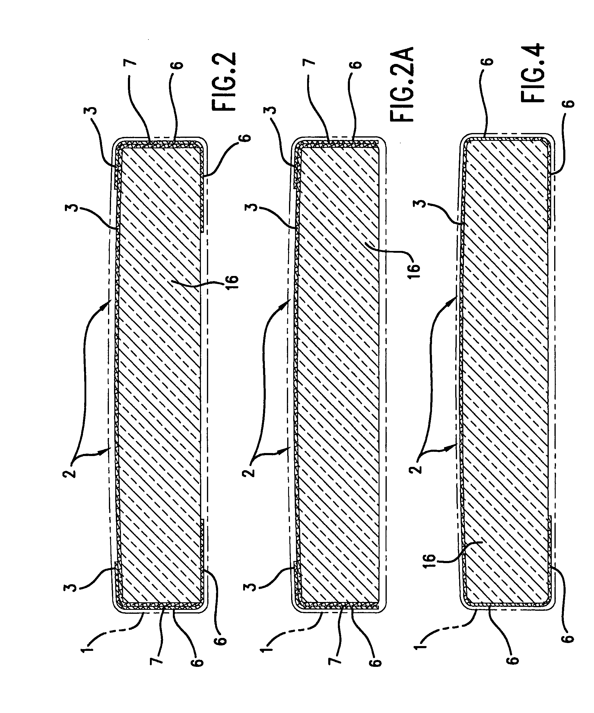
[0042]FIG. 1 is a perspective view of a mattress with one embodiment of the cooling surface shown in the central position of the mattress 16. The cooling portion may be at any position on the mattress, depending on the portion of the anatomy to be cooled. In the central position shown, the device is positioned to cool the sacral and low back region of the body.

[0043] In this embodiment, the device is positioned beneath the ticking 1. In other embodiments, the device is positioned as an overlay on top of the ticking or other surface.

[0044] Oriented across the mattress in the support region 2 are a series of highly thermally conductive materials 3. These conductive materials may be pitch-based carbon fibers or polymers with thermal conductivities in excess of 40 W / m-K. Although the predominant orientation is across the mattress (i.e., perpendicular to the long axis of the mattress), they have a zig-zag or somewhat sinusoidal or wavy configuration. This geometry allows the support re...


PUM


Abstract

Steady-state cooling of the skin is achieved by a support surface without requiring external power or circulation of air. Heat is transferred from via a thermally conductive layer or layers of material(s) that are soft, pliable, and comfortable to sit or lie on. The layer is connected to conductive materials that transport heat and diffuse the heat to a cooler environment.

Description

CROSS-REFERENCE TO RELATED APPLICATIONS [0001] This application is a continuation-in-part of pending U.S. application Ser. No. 11 / 147,707, filed Jun. 8, 2005, which claims priority to U.S. Provisional Application Ser. No. 60 / 577,765, filed Jun. 8, 2004; and claims priority to PCT Application No. PCT / US2004 / 003628, filed Feb. 10, 2004, which claims priority to U.S. Provisional Application Ser. No. 60 / 478,487 filed Jun. 13, 2003 and U.S. Provisional Application Ser. No. 60 / 491,954 filed Aug. 1, 2003 and U.S. Provisional Application Ser. No. 60 / 499,796 filed Sep. 3, 2003; and claims priority to PCT Application No. PCT / US2005 / 019413, filed Jun. 2, 2005.FIELD OF THE INVENTION [0002] The present invention relates to support surfaces that remove heat from human or other mammalians. BACKGROUND OF THE INVENTION [0003] Bedsores, or decubitus ulcers, can be a serious problem in bedridden or wheelchair-bound patients, particularly for people who are paralyzed, emaciated, post-surgical, elderly,...

Claims


Application Information

Patent Timeline
IPC IPC(8): A61F7/00A61F7/10
CPCA61F7/10A61F2007/0246A61F2007/0075A61F2007/0001A61F7/0097A61F2007/0057
Inventor LACHENBRUCH, CHARLES ARTHUR
Owner LACHENBRUCH CHARLES ARTHUR
Why Eureka
Try Eureka