
Method for Protecting a Logic or Mathematical operator Installed in an Electronic Module with a Microprocessor, as well as the Associated Embarked Electronic Module and the System

a technology of electronic modules and logic or mathematical operators, applied in the direction of instruments, power supplies for data processing, liquid/fluent solid measurements, etc., can solve the problems of fraud, increased identification difficulty, and even more difficult identification of sequences

Active Publication Date: 2008-01-17
GEMPLU
View PDF20 Cites 7 Cited by
  • Summary
  • Abstract
  • Description
  • Claims
  • Application Information

AI Technical Summary

Benefits of technology

[0006]The object of the present invention is to protect certain vulnerable operations inside a program, especially logic or mathematical operators or similar operational circuits rendering them difficult, even more difficult, to identify.
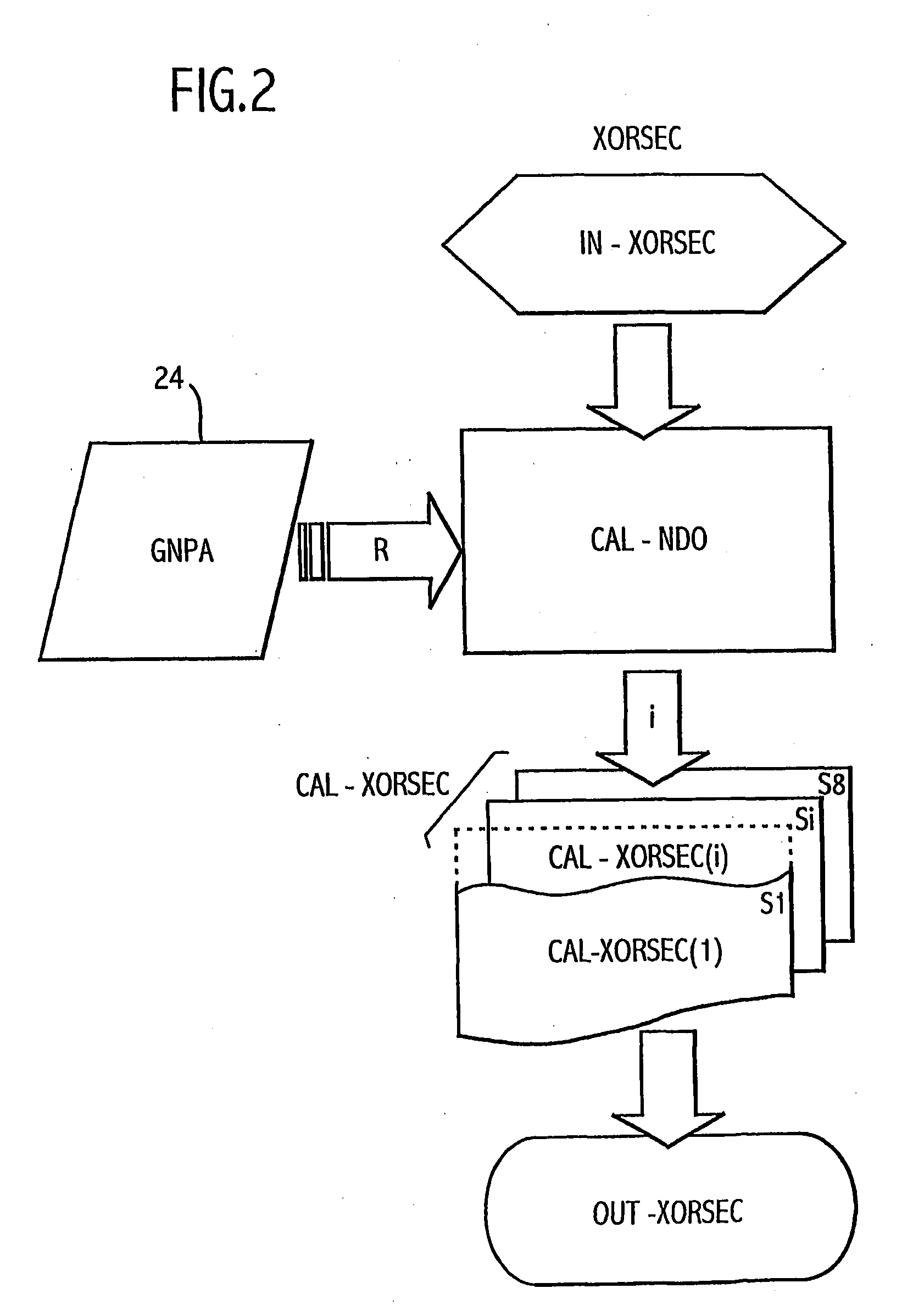
[0010]According to a first variant of the invention, the order number in its entirety of the selected sequence is determined according to certain parameters of the current program being executed and / or a random parameter advantageously obtained from a generator of pseudo-random numbers. This scrambling mechanism for scrambling sequences proves to be extremely effective when the operator to be protected is repeated several times in a program, as for example the XOR operator in an encryption / decryption processing.

Problems solved by technology

Thus, the difficulty of identification is further increased by the multiple changes of the sequence of operations replacing the operator to be protected during the execution of a given program.
Advantageously, the set of sequences comprises at least four equivalent sequences and preferably eight equivalent sequences, which makes even more difficult identification of the sequence as the operator sought by fraudulent persons.

Method used


Image

  • Method for Protecting a Logic or Mathematical operator Installed in an Electronic Module with a Microprocessor, as well as the Associated Embarked Electronic Module and the System
  • Method for Protecting a Logic or Mathematical operator Installed in an Electronic Module with a Microprocessor, as well as the Associated Embarked Electronic Module and the System

Examples


Embodiment Construction

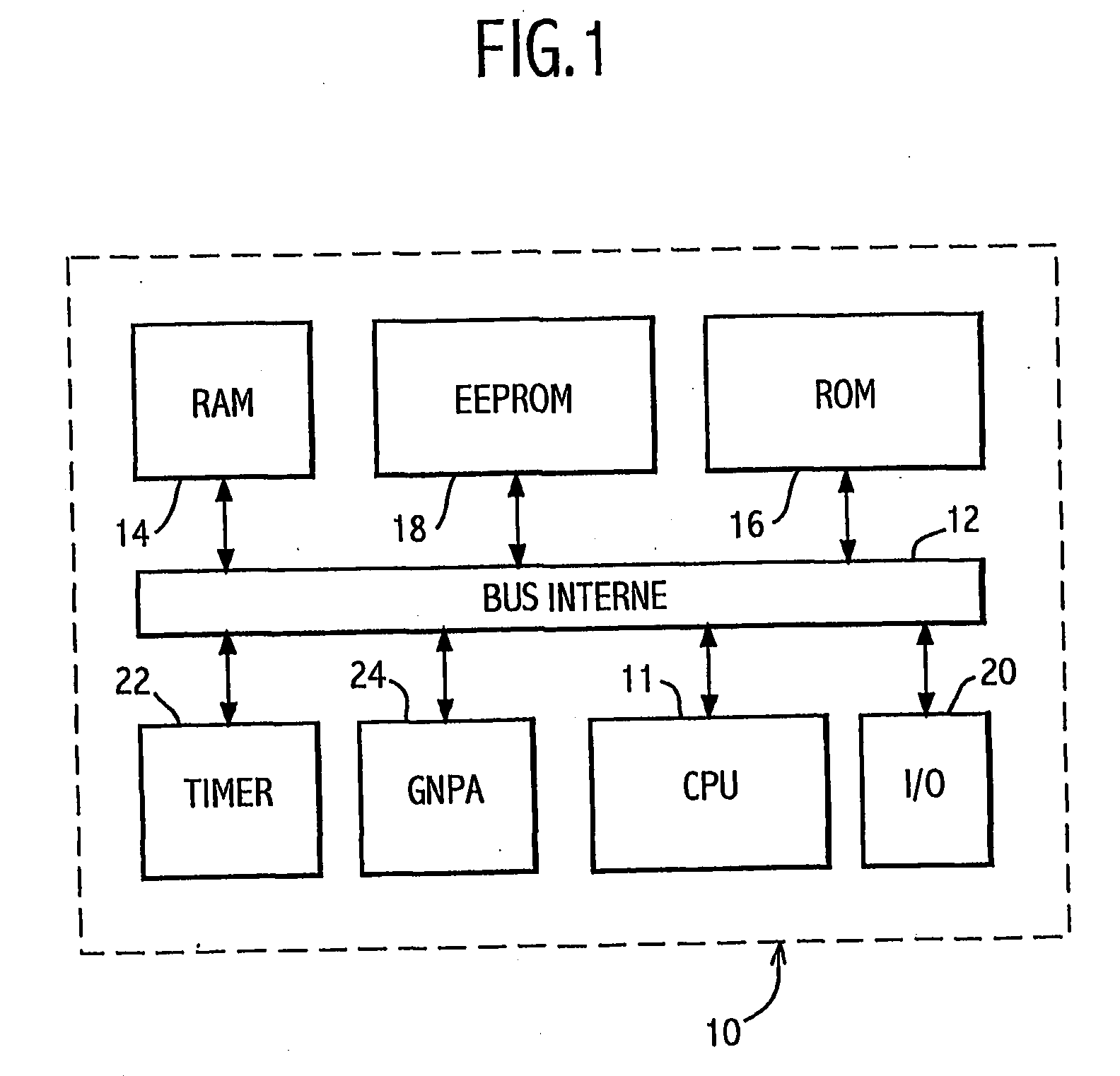
[0044]The monolithic electronic module 10 with a microprocessor shown on FIG. 1 according to the present invention and described by way of non-restrictive example generally comprises one microprocessor or central unit CPU 11 connected bidirectionally by an internal bus 12 to a live RAM memory 14, a dead ROM memory 16, an EEPROM memory 18 and an I / O input / output interface 20. The module 10 also comprises a Timer 22 with automatic resetting (in an optional variant) and a generator of pseudo-random numbers GNPA 24 connected to the internal bus 12.

[0045]Application programs are installed at ROM 16, such as applications of bank card transactions or medical card applications which for reasons of confidentiality and protection comprise encryption / decryption, operator authentication or transaction validation sub-program in which the XOR operator is frequently present, especially for carrying out comparisons octet by octet.

[0046]As regards execution of the XOR operator, this operator most co...


PUM


Abstract

The method for protecting a logic or mathematical operator of the NOR operator type, able to be used for executing a program in a microprocessor electronic module wherein the execution of the NOR operator is replaced by the execution (CAL-XORSEC(1) of a sequence Si operations having for final result a result identical to that of the XOR function.The sequence of operations Si composed of elementary operations with AND, OR and NOT is selected at each XOR operator from a set of eight equivalent sequences (S1 to S8) after determination CAL-NDO) of an order number NDO=1 according to the parameters of the program and / or a random parameter R supplied by a pseudo-random number generator (14).

Description

FIELD OF THE INVENTION[0001]The present invention concerns the protection of embarked systems comprising one or several electronic modules incorporating at least one microprocessor, a ROM type memory containing at least one program to be executed and input / output means for communicating with the outside world. Certain modules also comprise other accessory circuits, such as RAM and EEPROM memories for more elaborate applications and are also known under the name of microcontrollers.[0002]These modules are most often embodied in the form of a monolithic electronic microcircuit or chip. These modules can be used firstly as such once physically protected and mounted for example on a portable smart card object, microcircuit card or similar element able to used in various domains, especially those relating to bank and / or commercial cards, mobile radiotelephony, paying television, health and transport, and secondly in other embarked systems ranging from relatively simple systems, such as s...

Claims


Application Information

Patent Timeline
IPC IPC(8): G06F19/00
CPCG06F21/75G06F21/755
Inventor GIRAUD, NICOLASBROHL, ABRAHAMHAMEAU, PATRICE
Owner GEMPLU
Learn More