Electronic component with heat transfer by boiling and condensation and method for producing same

a technology of electronic components and heat transfer, applied in the direction of instruments, lighting and heating apparatus, and semiconductor/solid-state device details, etc., can solve the problems of thermal coupling and limit the amount of heat to be removed, and achieve the effect of improving the efficiency of an electronic componen

Inactive Publication Date: 2008-01-24
COMMISSARIAT A LENERGIE ATOMIQUE ET AUX ENERGIES ALTERNATIVES
View PDF4 Cites 41 Cited by
  • Summary
  • Abstract
  • Description
  • Claims
  • Application Information

AI Technical Summary

Benefits of technology

[0010]The object of the invention is to improve the efficiency of...

Problems solved by technology

The problem of thermal coupling arises in the same way in a Seebeck effect thermoelectric converter, in which the heat has to be removed at the level of the cold source to maintain the thermal gradient generating the electric current, as in a Peltier...

Method used


Image

  • Electronic component with heat transfer by boiling and condensation and method for producing same
  • Electronic component with heat transfer by boiling and condensation and method for producing same
  • Electronic component with heat transfer by boiling and condensation and method for producing same

Examples


Embodiment Construction

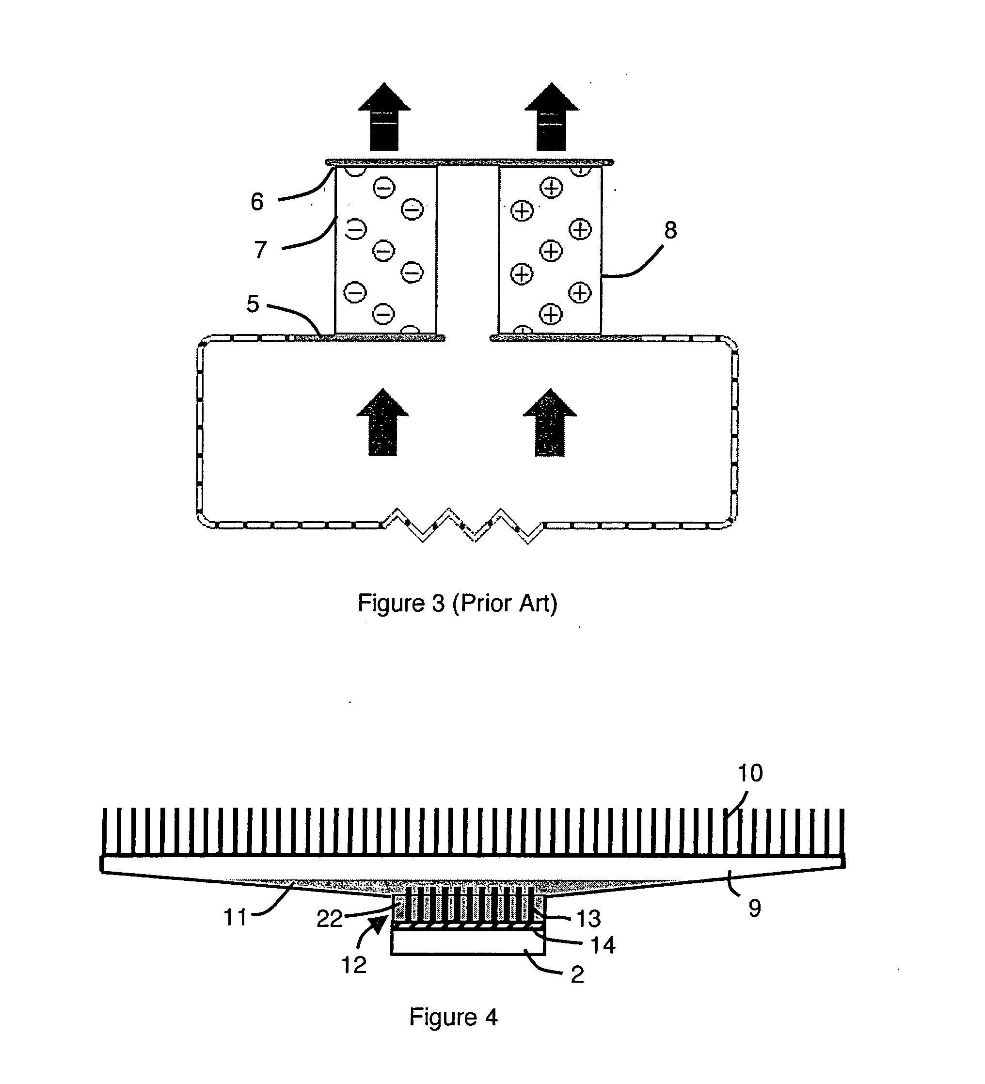
[0023]In the two alternative embodiments of the invention represented in FIGS. 4 and 5, heat transfer between the component 2 to be cooled and the ambient air is performed by a heat pipe 9, i.e. by means of a heat transfer by boiling and condensation taking place in a closed circuit with return of the fluid either by gravity or by capillarity. The heat pipe can have any suitable known configuration.

[0024]For example, the heat pipe 9 of FIG. 4 has the shape of an upwardly tapered chamber preferably presenting fins 10 on the external face of its top wall. The heat pipe 9 of FIG. 5 for its part is formed by a vertical cylindrical tube preferably comprising fins 10 on the external face of its side wall.

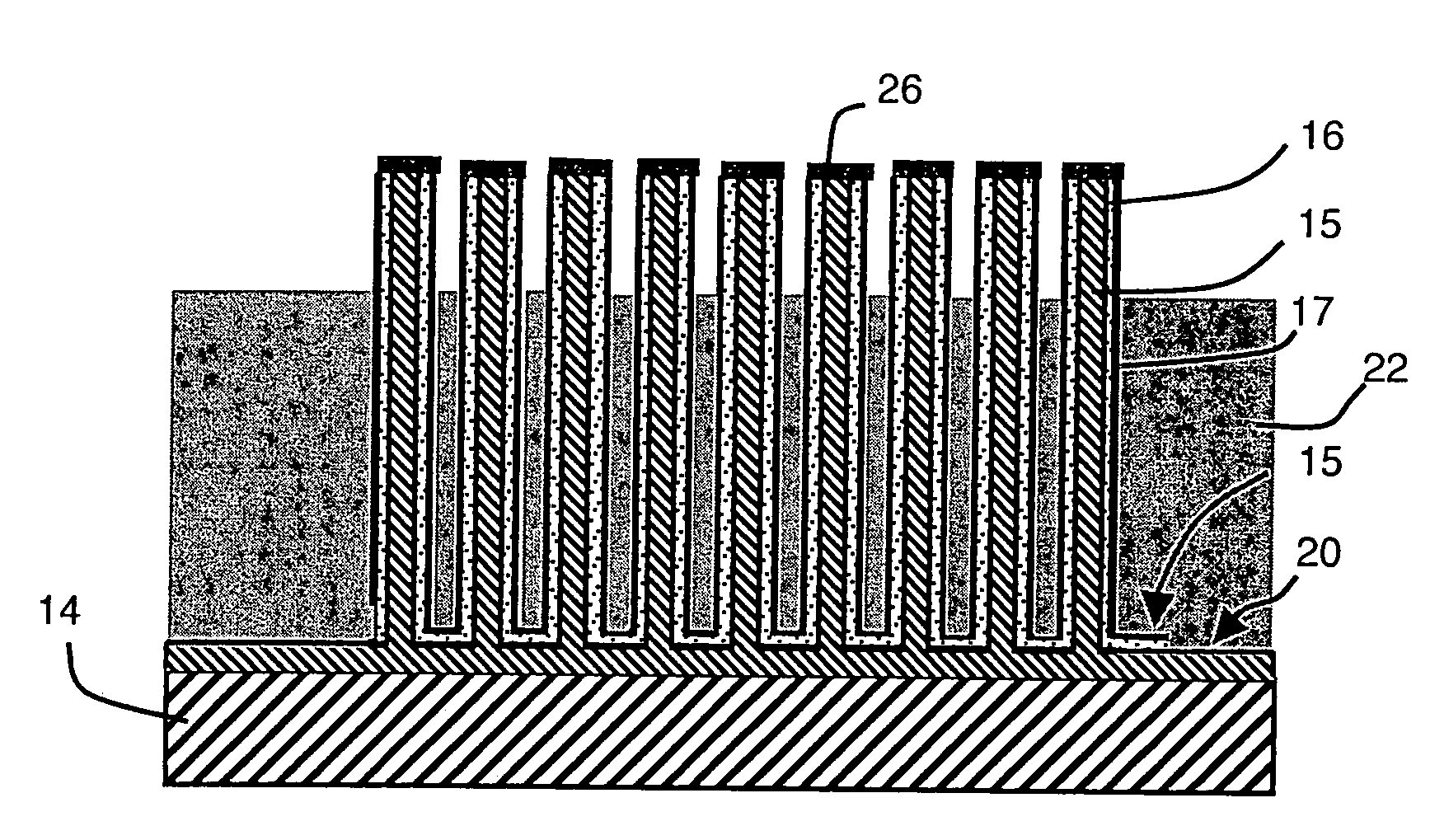
[0025]In FIGS. 4 and 5, the component 2 to be cooled constitutes the hot source of a nanowire-based thermoelectric converter comprising a plurality of nanowires 13 formed on a base substrate 14. The free ends of the nanowires reject the heat to the cold source constituted by the ambient a...


PUM

PropertyMeasurementUnit
Thicknessaaaaaaaaaa
Electrical conductoraaaaaaaaaa
Metallic bondaaaaaaaaaa

Abstract

The electronic component with heat transfer by boiling and condensation comprises heat exchange surfaces immersed in a heat conducting fluid constituted by the free ends of nanowires of a thermoelectric converter. An electrically insulating coating material with a low thermal conduction partially covers the nanowires above the heat conducting fluid. Each nanowire forms a thermocouple composed of two coaxial branches made from materials of different natures separated by a layer of electrically insulating material and electrically connected individually to the free end of the nanowire.

Description

BACKGROUND OF THE INVENTION[0001]The invention relates to an electronic component with heat transfer by boiling and condensation comprising heat exchange surfaces immersed in a heat conducting fluid, and a method for producing one such component.STATE OF THE ART[0002]As represented in FIG. 1, a cooling device can be formed by an electronic component, for example a thermoelectric converter 1, arranged on a component to be cooled constituting a heat source 2 and associated with a fin cooling assembly 3, possibly in forced convection by means of a fan 4.[0003]Electronic components used as thermoelectric converters are conventionally formed by thermocouples (FIGS. 2 and 3) thermally connected in parallel between respectively hot and cold sources 5 and 6, each thermocouple being made up of two branches 7 and 8 made from metallic or semi-conducting materials of different natures (for example respectively of n-type and p-type) electrically connected in series. The heat flux passing through...

Claims


Application Information

Patent Timeline
IPC IPC(8): F28D15/02B23P15/26
CPCF28D15/02F28F3/022H01L23/427H01L35/30Y10T29/49353H01L2924/0002Y10T436/114998H01L2924/00H10N10/13
Inventor GRUSS, JEAN-ANTOINEPLISSONNIER, MARC
Owner COMMISSARIAT A LENERGIE ATOMIQUE ET AUX ENERGIES ALTERNATIVES
Why Eureka
Try Eureka