Probe Head Manufacturing Method

a manufacturing method and technology of a probe head, applied in the direction of measuring devices, decorative surface effects, instruments, etc., can solve the problems of measurement failure or information reading failure, information reading failure to be a serious problem, and thickness is extremely thin, so as to increase the uniformity of frequency and prevent measurement failure

Inactive Publication Date: 2008-01-24
PIONEER CORP +1
View PDF7 Cites 30 Cited by
  • Summary
  • Abstract
  • Description
  • Claims
  • Application Information

AI Technical Summary

Benefits of technology

[0011] In order to solve the above-exemplified problems, it is therefore an object of the present invention to provide a manufacturing method of a probe head, which can uniform the frequency

Problems solved by technology

If the beam vibrates, the tip end floats by little and little from the surface of the ferroelectric substance, which incompletes the scanning and which likely causes measurement failure or information reading failure or the like.
If the tip end passes on the unevenness of the ferroelectric substance surface during the high-speed scanning, large vibration occurs in the cantilever and it takes a time to converge the vibration, which likely causes the information reading failure to be a serious problem.
However, the beam thickness is extremely thin, such as several nanometers to several micrometers, and moreover, if the beam thickness varies by several nanometers, the frequency of the vibr

Method used


Image

  • Probe Head Manufacturing Method
  • Probe Head Manufacturing Method
  • Probe Head Manufacturing Method

Examples


Embodiment Construction

[0045] Hereinafter, the best mode for carrying out the invention will be explained, with reference to the drawings.

(Basic Structure of Probe Head)

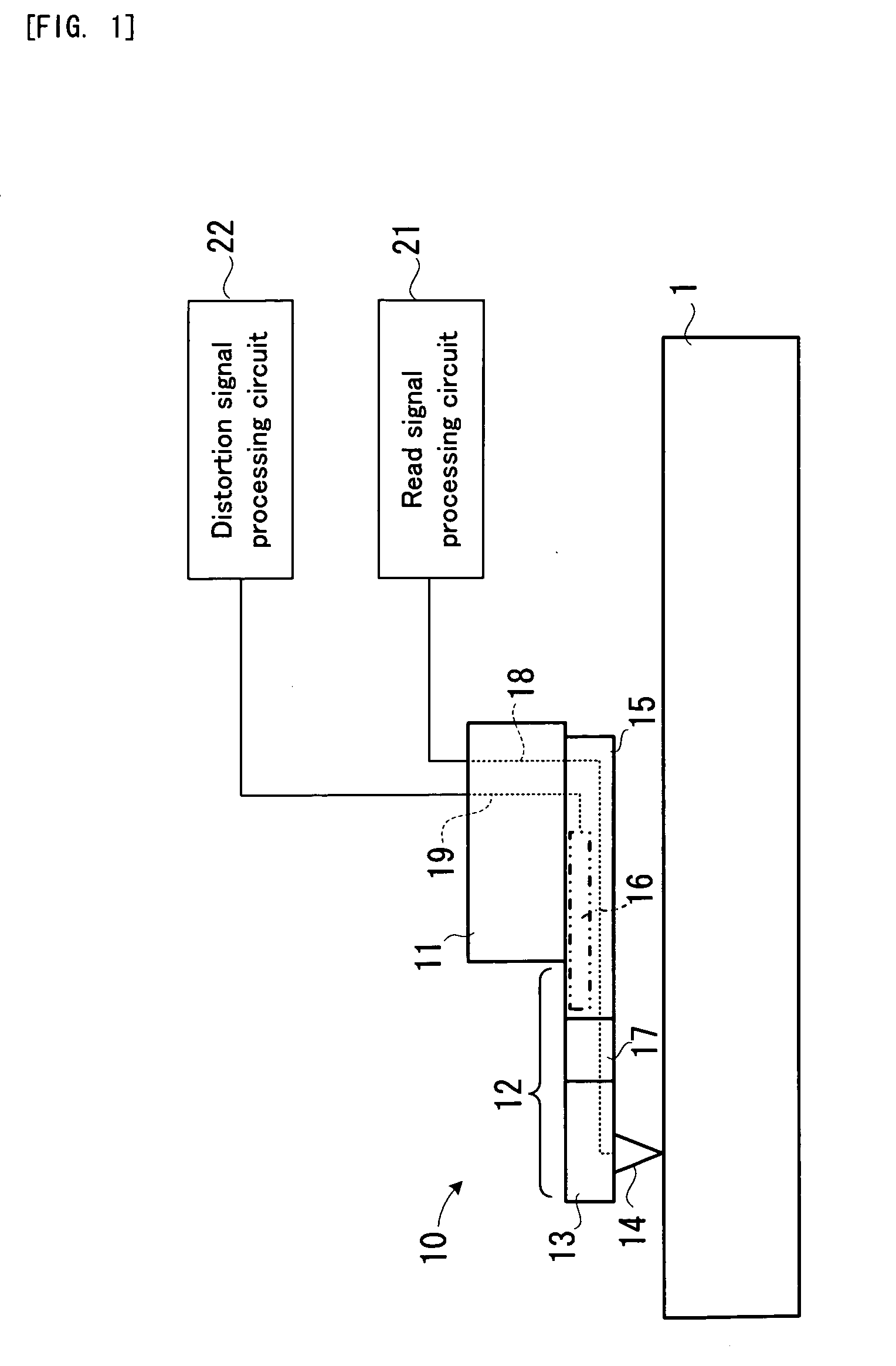
[0046]FIG. 1 shows the basic structure of a probe head. In FIG. 1, a probe head 10 is the cantilever type probe head used in the SNDM and the SNDM information recording. The probe head 10 is provided with: a head substrate 11; and a beam (cantilever) 12 extending from the head substrate 11.

[0047] On the tip end side of the beam 12, a tip support portion 13 is formed. The tip support portion 13 supports a diamond tip 14 which is sharp. On the base end side of the beam 12, a circuit portion 15 is formed. In the circuit portion 15, a distortion detection circuit 16 is formed. In the beam 12, an insulating wall portion 17 is formed between the tip support portion 13 and the circuit portion 15.

[0048] The tip support portion 13 and the diamond tip 14 are both low resistant and substantially electric conductors. Moreover, the distortion dete...


PUM


Abstract

A beam (32) of a probe bead (30) having a uniform thickness is formed by using a silicon layer (64) of a SOI substrate. The beam of the probe head is formed by growing a boron-doped diamond and non-doped diamond on a processing substrate, respectively.

Description

TECHNICAL FIELD [0001] The present invention relates to a manufacturing method of a probe head used for a scanning probe microscope apparatus or a scanning probe information recording / reproducing apparatus or the like, for example. BACKGROUND ART [0002] A scanning probe microscope (SPM) is known as an apparatus capable of measuring the shape, property, or the like of the surface of a sample, in nano scale. In particular, there are widely spread a scanning tunneling microscope (STM) for scanning the surface of a sample with a probe and performing measurements by using a tunneling current which flows between the probe and the sample, and also an atomic force microscope (AFM) for scanning the surface of a sample with a probe and performing measurements by using an atomic force which is applied between the probe and the sample. [0003] Recently, as a kind of the scanning probe microscope, there has been developed a scanning nonlinear dielectric microscope (SNDN) for reading the nonlinear...

Claims


Application Information

Patent Timeline
IPC IPC(8): B44C1/22G01Q10/00G01Q70/14G01Q70/16G01Q80/00
CPCB82Y35/00G01Q80/00G01Q70/16G01Q70/14
Inventor TAKAHASHI, HIROKAZUONO, TAKAHITOESASHI, MASAYOSHI
Owner PIONEER CORP
Why Eureka
Try Eureka