Thin stator, eccentric motor and axial air-gap brushless vibration motor equipped with the same

a brushless vibration and eccentric motor technology, applied in the direction of generator/motor, mechanical energy handling, magnetic circuit shape/form/construction, etc., can solve the problems of no practical purpose, difficult to find space for disposition, and decrepit mounting efficiency

Inactive Publication Date: 2008-01-24
TOKYO PARTS IND CO LTD
View PDF6 Cites 80 Cited by
  • Summary
  • Abstract
  • Description
  • Claims
  • Application Information

AI Technical Summary

Benefits of technology

[0021]With such a constitution, since the detent torque part is included within the stator base, its thickness can be substantially ignored, and a detent torque part can be set at a position without regard to the inner diameter of the air-core armature coil inner. For this reason, the air-core armature coil inner diameter can be made small, enabling a sufficient of number of windings to be secured and sufficient starting torque to be achieved and preventing members constituting the stator from overlapping with one another. As a result, the stator can be very thin.
[0023]With such a constitution, the influence of bracket magnetic force can be suppressed, enabling the magnetism of the detent torque generation member to be reduced.
[0025]With such a constitution, no additional detent torque generation member is necessary, enabling reduction in the number of members used for a thin stator.
[0027]With such a constitution, because a tungsten eccentric weight can be easily soldered on the surface, spot welding, adhesion and the like are sufficiently reliable. Therefore, a thin rotor with sufficient impact resistance and high reliability can be achieved.

Problems solved by technology

However, a motor according to such design tends to be long in the lateral direction, decreasing mounting efficiency in the case of a printed wiring board in the SMD style.
Further, because it is a cored type, such motor invariably becomes thick and thus serves no practical purpose.
Consequently, it is difficult to find space for disposition, and the configuration operates against the goal of forming a thinner motor.
But increasing width makes the position of a detent torque generation member unstable, and decreasing width, on the other hand, will result in a substantial sacrifice of thickness.
However, such motor is problematic in that its coil inner diameter is limited, restricting the number of windings on a coil.
With a coil having a small inner diameter, such displacement angle cannot be made large.
However, when thickness is to be less than 2 mm, rotor thickness and drive circuit member thickness are a problem, with the natural result being that the thickness of the rotor is sacrificed, making it difficult to secure adequate vibration.
However, adhesion is not sufficient to achieve reliable impact resistance.
Also, because tungsten has a higher melting point than a metal to be welded thereto, when welding by laser, it is difficult to weld tungsten to, for example, the above magnetic iron alloy.

Method used


Image

  • Thin stator, eccentric motor and axial air-gap brushless vibration motor equipped with the same
  • Thin stator, eccentric motor and axial air-gap brushless vibration motor equipped with the same
  • Thin stator, eccentric motor and axial air-gap brushless vibration motor equipped with the same

Examples


first embodiment

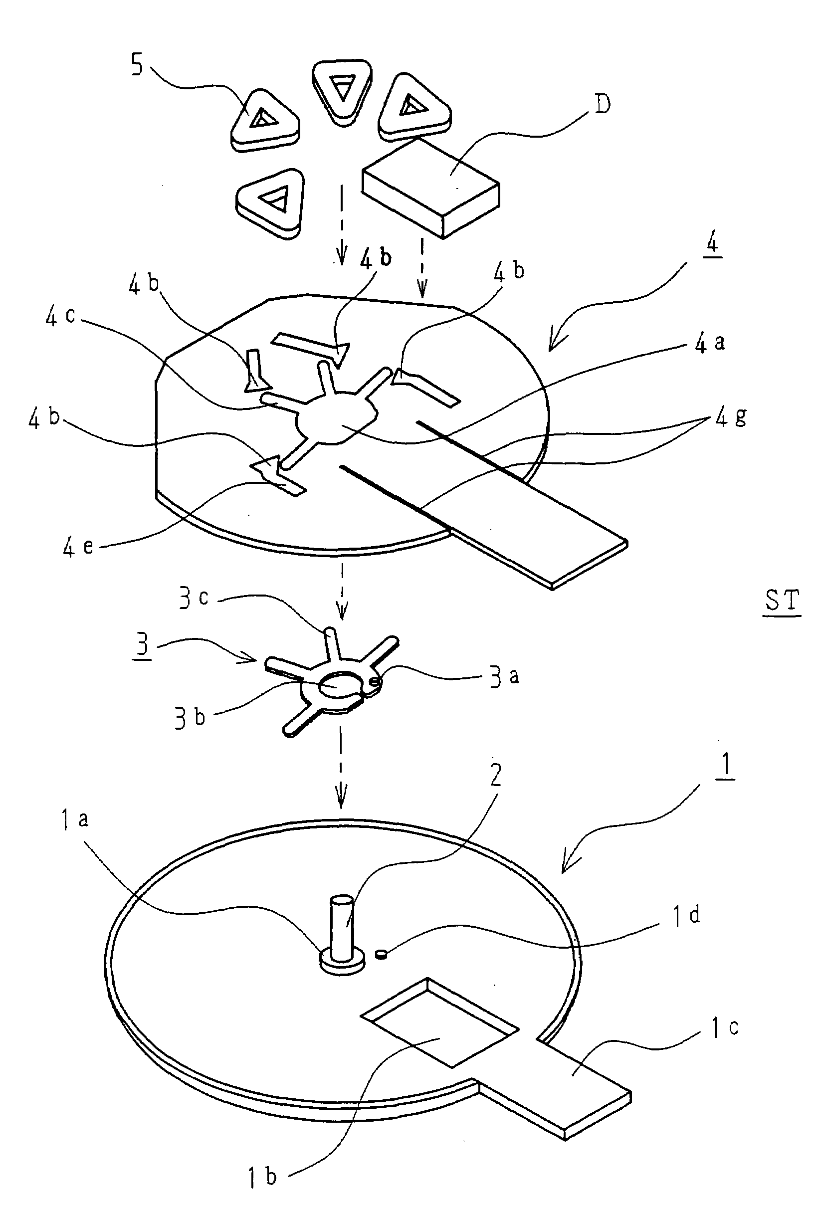
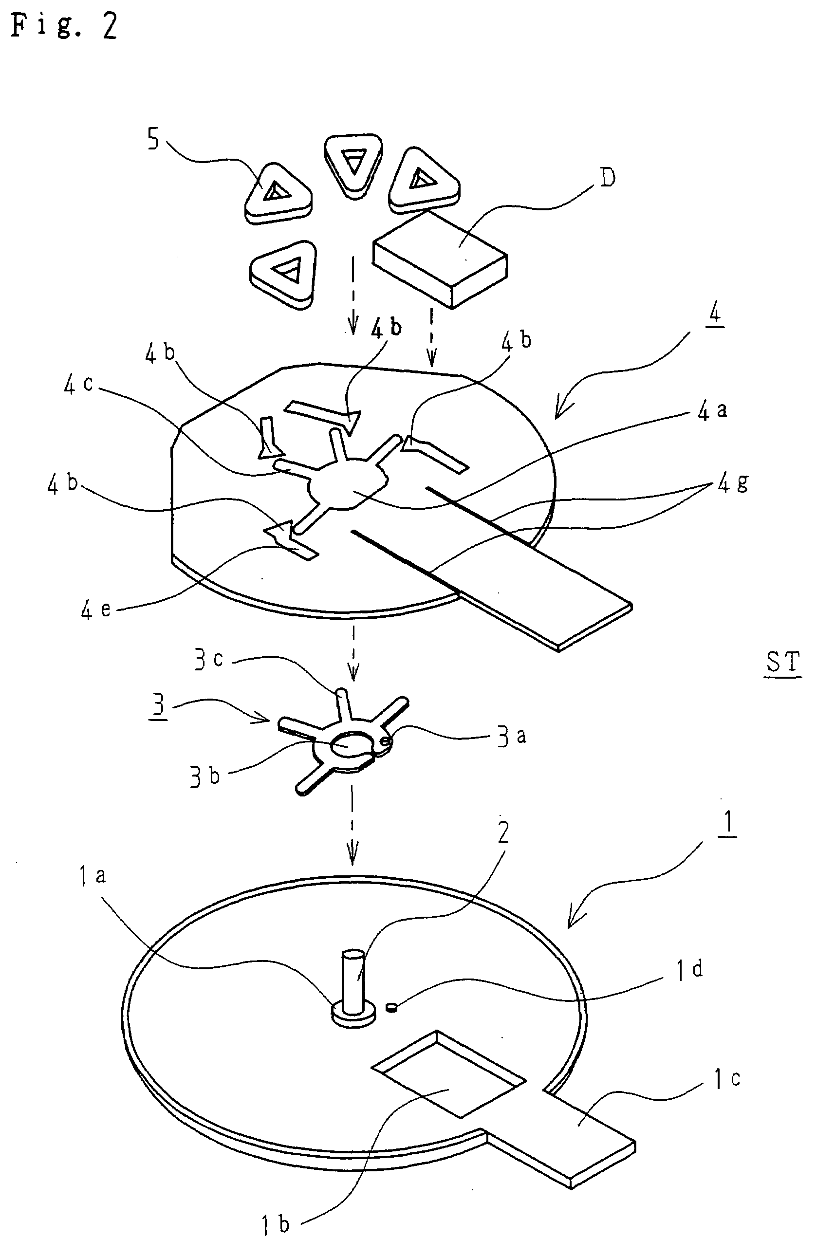
[0044]FIGS. 1-2 shows, as a component constituting a stator ST of the present invention, a thin bracket 1 formed of a nonmagnetic or weak magnetic sheet with a thickness of about 0.15 mm, and comprising a shallow burring 1a pressed so as to penetrate therethrough and stand at the center thereof. A shaft 2 is fitted into the shallow burring 1a and fixed thereto by application from the outside of laser, thus forming a shaft bearing portion.

[0045]The bracket 1 further has a rectangular through hole 1b as a recess, and a power feed terminal installation part 1c extending laterally therefrom.

[0046]The bracket 1 has, on the upper surface thereof, a detent torque generation member 3 formed of a magnetic stainless sheet with a thickness of about 0.1 mm, which is disposed on the burring 1a by the mating of a positioning hole 3a with a protrusion 1d on the bracket 1 concurrently with the fitting of a central through hole 3b on the burring 1a.

[0047]The detent torque generation member 3 furthe...

second embodiment

[0060]An eccentric rotor R facing the stator ST across an axial air gap is configured as shown in FIG. 3. Eccentric rotor R comprises an axial air-gap magnet M, an eccentric weight W having an arc-shaped main component disposed partly around the magnet M, a magnetic metal rotor case 6 with a thickness of 0.15 mm to which the foregoing are fixed, and a flange type bearing 7 fixed at the center of rotation of the rotor case 6 by welding or the like.

[0061]FIG. 4 shows a fixed shaft type axial air-gap brushless vibration motor of a coreless slotless type comprising such stator ST and eccentric rotor R. Except for certain parts, explanations have already been given for the constitution of the stator, and are here omitted.

[0062]The rotor case 6 of the eccentric rotor R comprises a flat part 6d to which the upper surface of the magnet M is adhered, an outer diameter hanging portion 6e continuing therefrom, and a hanging portion on the inner diameter side 6f that supports the bearing 7.

[006...

third embodiment

[0070]FIG. 5 shows a variation of FIG. 4, and is an embodiment suitable for cases where such an axial air-gap motor is used as a central magnetic pole for an electromagnetic acoustic converter.

[0071]The difference from FIG. 4 is as follows. A lower part of an outer case 88 circumferentially extends so as to serve as a flange 88a, and connects with the stator bracket 11 with a protrusion and recess joint K, and a magnetic body 88m is disposed around the outer case 88. In the drawing, Mg is speaker-side excitation magnet, C is an excitation coil, SS is a vibration thin plate, and H is a speaker housing.

[0072]Here, the outer case 88 is configured such that at least a ceiling is nonmagnetic so as to prevent leaked magnetic flux from the speaker-side excitation magnet Mg from affecting the rotor magnet M, and the magnetic flux of the excitation magnet Mg is stopped by the magnetic body 88m.

[0073]If radial direction size poses a problem when separately disposing the magnetic body 88m, th...


PUM


Abstract

A stator includes a bracket having a shaft bearing portion at a center, a stator base including a flexible printed wiring board outwardly attached to the shaft bearing portion, single-phase air-armature coils disposed on the stator base, and a drive circuit member disposed on the stator base so as not to overlap with the single-phase air-core armature coils. The bracket has a through hole at the section corresponding to the bottom of the drive circuit member. The stator base is embedded at least partly in the thickness direction in the through hole and fixed using a resin, and a detent torque generation member is contained in, and is no thicker than, the stator base.

Description

BACKGROUND OF THE INVENTION[0001]The present invention relates to a thin stator suitable for use as silent call means for a portable communication device and the like, an eccentric rotor, and an axial air-gap brushless vibration motor equipped with the same.[0002]Flat axial air-gap brushless vibration motors have been previously proposed, for example, in Laid-open Japanese Utility Model Application No. H4-137463 and Laid-open Japanese Patent Application No. 2002-143767, and include a motor of a coreless slotless type comprising a bearing.[0003]Known brushless vibration motors, for example, as disclosed in Laid-open Japanese Patent Application No. 2000-245103, are equipped with a drive circuit, and include a noncircular motor of a cored type comprising a plurality of equidistantly disposed salient poles and an armature coil wound therearound, and a drive circuit member disposed in a stator.[0004]However, a motor according to such design tends to be long in the lateral direction, decr...

Claims


Application Information

Patent Timeline
Patent Type & Authority Applications(United States)
IPC IPC(8): H02K11/00H02K7/06
CPCH02K1/182H02K3/26H02K3/52H02K29/03H02K5/225H02K7/06H02K21/24H02K5/163Y10S310/06
Inventor YAMAGUCHI, TADAOSOHARA, KATSUHITO
Owner TOKYO PARTS IND CO LTD
Why Eureka
Try Eureka