Surface Acoustic Wave Resonator and Surface Acoustic Wave Filter Using the Same

a surface acoustic wave and resonator technology, applied in the direction of impedence networks, electrical devices, etc., can solve the problems of limiting the improvement of insertion loss and steepness, and the inability to secure the q-factors of the resonator, so as to improve the steepness of the filter characteristic and reduce the insertion loss of the surface acoustic wave filter

Active Publication Date: 2008-01-24
SKYWORKS PANASONIC FILTER SOLUTIONS JAPAN
View PDF7 Cites 13 Cited by
  • Summary
  • Abstract
  • Description
  • Claims
  • Application Information

AI Technical Summary

Benefits of technology

[0008] According to the present invention, Q-factors of the surface acoustic wave resonators can be improved. The insertion loss of the surface acoustic wave filter can be reduced, and the steepness of the filter characteristic can be improved.

Problems solved by technology

The structure described above has a problem that sufficient Q-factors of the resonators cannot be secured when the frequency increases.
Furthermore, when a filter is formed, there is a limit on improving insertion loss and steepness.

Method used


Image

  • Surface Acoustic Wave Resonator and Surface Acoustic Wave Filter Using the Same
  • Surface Acoustic Wave Resonator and Surface Acoustic Wave Filter Using the Same
  • Surface Acoustic Wave Resonator and Surface Acoustic Wave Filter Using the Same

Examples


embodiment 1

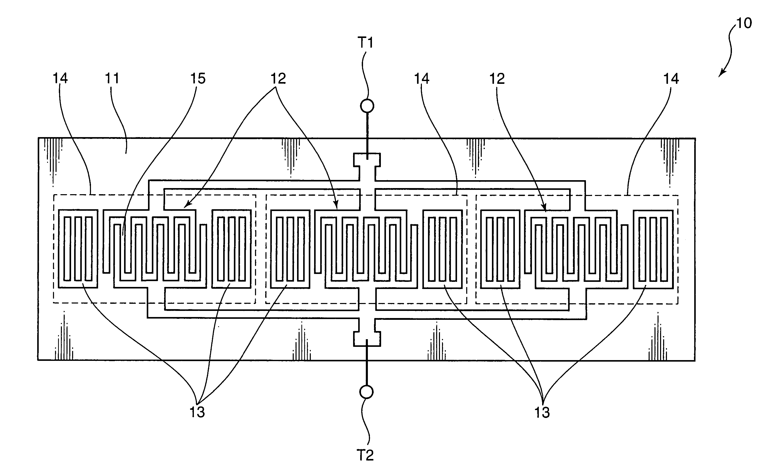
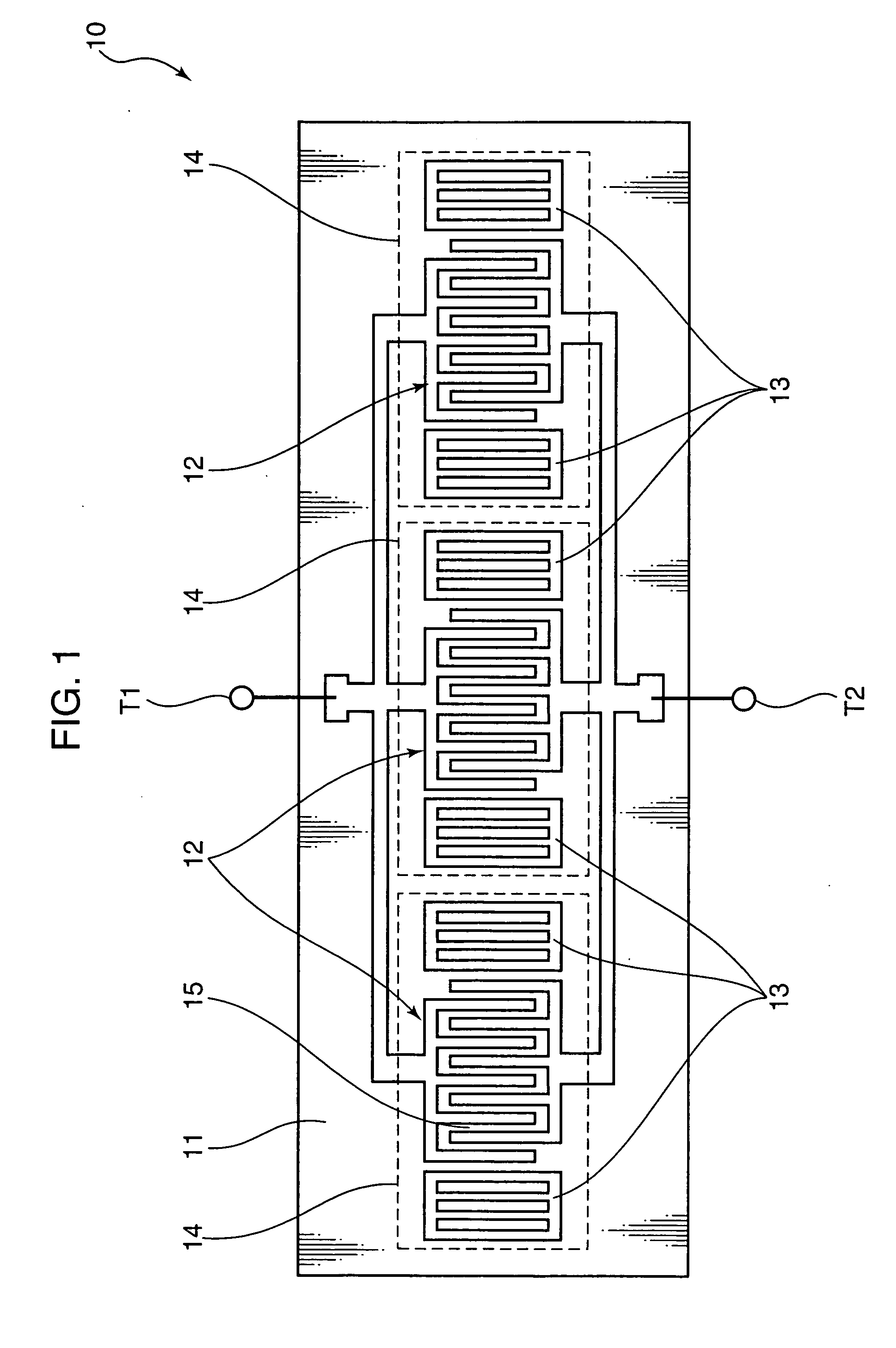
[0022] Hereinafter, Embodiment 1 of the present invention will be described. FIG. 1 is a diagram showing an exemplary structure of a surface acoustic wave resonator 10 according to Embodiment 1 of the present invention. The surface acoustic wave resonator 10 shown in FIG. 1 is a so-called one-port resonator. The surface acoustic wave resonator 10 includes a signal input terminal T1 for receiving a signal input from the outside, a signal output terminal T2 for outputting a signal to the outside, and a piezoelectric substrate 11 formed of 39° Y-cut, X-propagating lithium tantalate. On a surface of the piezoelectric substrate 11, three surface acoustic wave resonators 14 (surface acoustic wave resonators) are formed in line on the same surface acoustic wave propagation path.

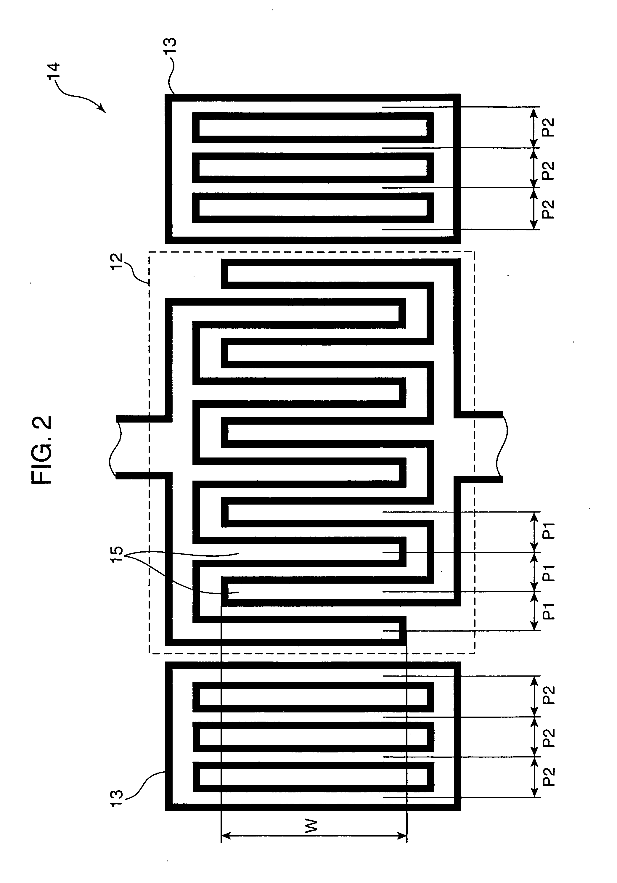
[0023] Each of the surface acoustic wave resonators 14 includes an IDT 12 and two reflectors 13 (reflecting electrodes) being adjacent to both ends of the IDT 12. Three surface acoustic wave resonators 14 having th...

embodiment 2

[0058] Hereinafter, Embodiment 2 of the present invention will be described. In Embodiment 1 of the present invention, a structure of a surface acoustic wave resonator is shown. Embodiment 2 is different from Embodiment 1 in that a structure of a ladder-type surface acoustic wave filter using such a surface acoustic wave resonator is shown.

[0059]FIG. 10 is a diagram showing an exemplary structure of a surface acoustic wave filter 21 according to Embodiment 2 of the present invention. The surface acoustic wave filter 21 shown in FIG. 10 is an example of a ladder-type surface acoustic wave filter, and includes a signal input terminal T1 for receiving a signal input from the outside, a signal output terminal T2 for outputting a signal to the outside, a ground terminal T3 for ground connection, and a piezoelectric substrate 11 formed of 39° Y-cut, X-propagating lithium tantalate. On a surface of the piezoelectric substrate 11, a series resonator 16 and a parallel resonator 17 are forme...

embodiment 3

[0068] Hereinafter, Embodiment 3 of the present invention will be described. Embodiment 3 is different from Embodiment 2 in that, while Embodiment 2 relates to a ladder-type surface acoustic wave filter using one terminal pair surface acoustic wave resonator, Embodiment 3 is applied to a surface acoustic wave filter using a multiple-port surface acoustic wave resonator.

[0069]FIG. 12 shows an exemplary structure of a surface acoustic wave filter 22 according to Embodiment 3 of the present invention. The surface acoustic wave filter 22 shown in FIG. 12 is an example of a ladder-type surface acoustic wave filter, and includes a signal input terminal T1 for receiving a signal input from the outside, a signal output terminal T2 for outputting a signal to the outside, a ground terminal T3 for ground connection, and a piezoelectric substrate 11 formed of 39° Y-cut, X-propagating lithium tantalate. On a surface of the piezoelectric substrate 11, a multiple-port surface acoustic wave resona...


PUM


Abstract

A Q-factor of a resonator at a high frequency is improved. An insertion loss of a filter using such a resonator and steepness of the filter are improved. A plurality of surface acoustic wave resonators including an interdigital transducer and reflecting electrodes provided on both sides thereof are connected in parallel on a piezoelectric substrate. Resonance frequencies of the surface acoustic wave resonators are rendered equal among all the resonators connected in parallel. In this way, Q-factor of resonance can be improved. A surface acoustic wave filter using such surface acoustic wave resonators is formed in order to improve the insertion loss and the steepness.

Description

TECHNICAL FIELD [0001] The present invention relates to a surface acoustic wave resonator and a surface acoustic wave filter using the same which are particularly used for cellular phones or the like. BACKGROUND ART [0002] Conventionally, such surface acoustic wave filters have had a structure as shown in FIG. 13. [0003] In a surface acoustic wave filter shown in FIG. 13, a series resonator 2 and a parallel resonator 3 which are surface acoustic wave resonators are formed on a piezoelectric substrate 1 and connected each other to provide a filter characteristic. As such resonators, multiple pairs of interdigital transducers or an interdigital transducer with reflecting electrodes being provided on both sides has been employed. [0004] As documents on the conventional art related to the present invention, Japanese Laid-Open Publication No. 2001-119260 is known, for example. [0005] The structure described above has a problem that sufficient Q-factors of the resonators cannot be secured...

Claims


Application Information

Patent Timeline
Patent Type & Authority Applications(United States)
IPC IPC(8): H03H9/145H03H9/25H03H9/64H03H9/02H03H9/76
CPCH03H9/02559H03H9/6496H03H9/6433H03H9/25H03H9/145H03H9/64H03H9/76
Inventor IGAKI, TSUTOMUSEKI, SHUN-ICHIIKEDA, KAZUO
Owner SKYWORKS PANASONIC FILTER SOLUTIONS JAPAN
Why Eureka
Try Eureka