Actuator for Manipulation of Liquid Droplets

Inactive Publication Date: 2008-01-24
HITACHI LTD
View PDF1 Cites 33 Cited by
  • Summary
  • Abstract
  • Description
  • Claims
  • Application Information

AI Technical Summary

Benefits of technology

[0011]When the device using the method mentioned above is applied to a chemical analysis apparatus and others, it is important to realize and measure various chemical reactions in accordance with the purpose and application of the user in the device. In other words, important matters include versatility for conveying a desired amount of liquid freely in two-dimensional directions, accuracy for precisely conveying the liquid to a desired position, and flexibility for enabling the mixed mounting with a sensor, a reactor and others. The following problems may be considered in the method for handling liquid as droplets by electrical control.
[0012]The devices in Patent Documents 1 and 2 and Non-Patent Documents 1, 2 and 4 have a structure where electrodes are individually disposed at each position for conveying the liquid. Therefore, as the number of conveying positions increase, the number of electrodes increases, and the number of wirings and switches for controlling the potential of each electrode also increases. The increase in the number of wirings and switches increases the load on the system devices, and it is hence desired to convey the liquid droplets with a smaller number of wirings and switches.
[0018]An object of the present invention is to provide a device capable of mixed mounting with a sensor and a reactor, stably conveying liquid droplets, and achieving accurate positioning of the droplets, even if the number of wirings and switches is reduced.
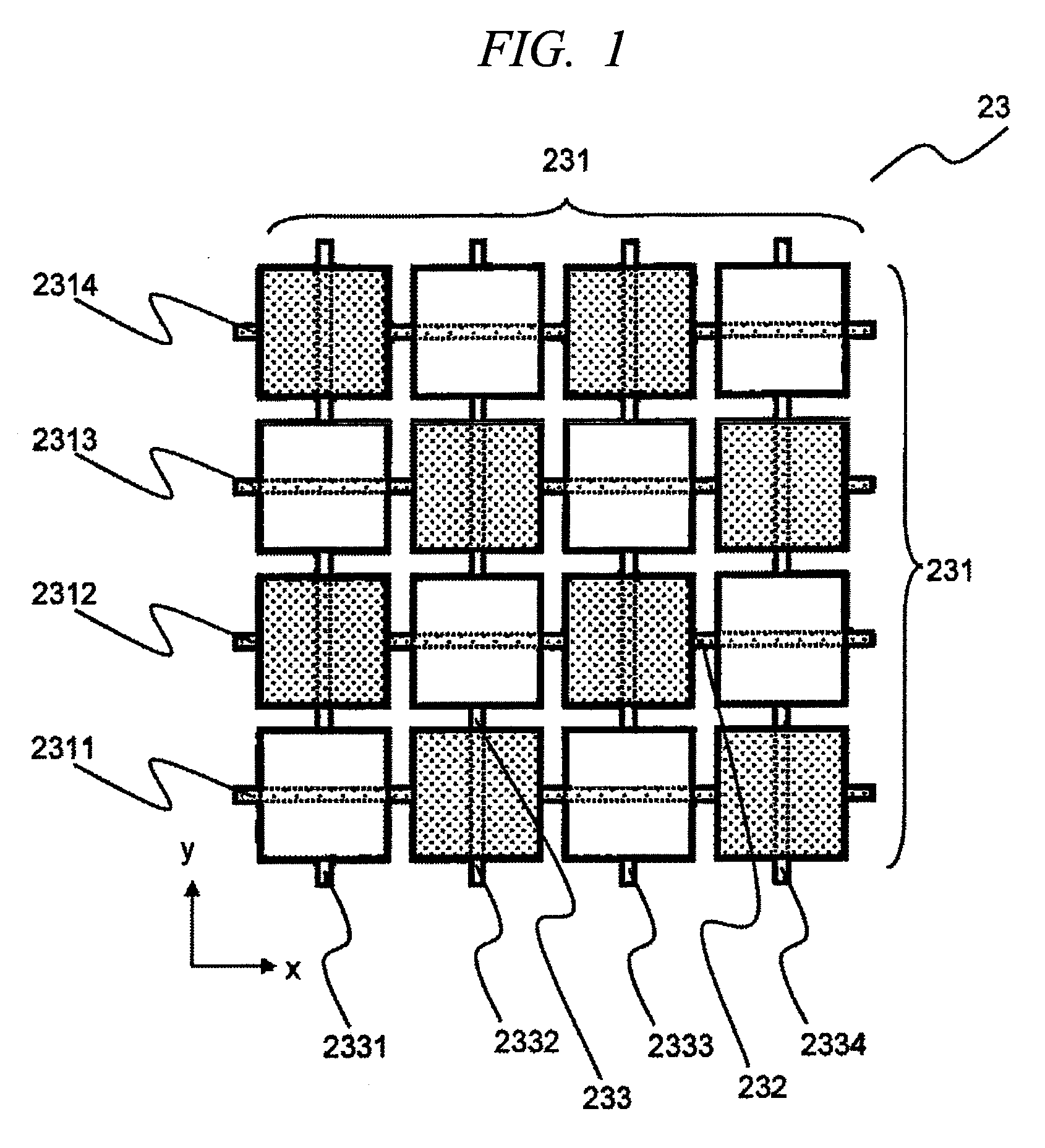
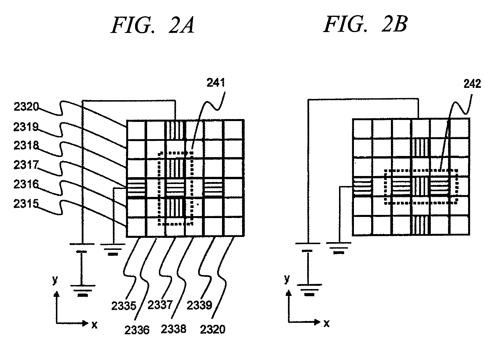
[0027]According to the present invention, electrodes covered with a dielectric are arranged two-dimensionally on a substrate surface, and a potential difference is applied to at least one pair of electrodes in a first axial direction and electrodes in a second axial direction among the electrode groups coupled in the first axial direction or the second axial direction, thereby conveying or stopping the liquid droplet. Since the device of the present invention does not require the switch for controlling the potential for each position for conveying the liquid, the number of switches required in the operation can be reduced, and the load on the system for controlling the operation can be decreased. Even if passage grooves are not formed on the device surface, the liquid droplet on the device can be conveyed in a route suited to the purpose of the user. Further, by switching the potential to be applied, deviation of the position of the conveyed liquid droplet can be corrected. Also, since it is not necessary to use a substrate having electrodes required to convey the liquid droplet in the upper part of the device, a substrate having a temperature regulator, sensor or reactor can be easily used. At this time, since the order and the time of contacting with the temperature regulator, sensor or reactor can be changed by controlling the conveying route of the liquid droplet, a chemical analysis apparatus suited to various purposes can be realized.

Problems solved by technology

The following problems may be considered in the method for handling liquid as droplets by electrical control.
However, since electrodes necessary for driving have to be disposed on both upper and lower substrates, it is difficult to mount the sensor and reactor together on the substrate.

Method used


Image

  • Actuator for Manipulation of Liquid Droplets
  • Actuator for Manipulation of Liquid Droplets
  • Actuator for Manipulation of Liquid Droplets

Examples


first embodiment

[0056]FIG. 3 is a diagram showing a structural example of an actuator for manipulation of liquid droplets of this embodiment. The actuator for manipulation of liquid droplets 1 of this embodiment is composed of a liquid conveying element 10 for holding a liquid droplet 15, a first axial voltage control device 16 and a second axial voltage control device 17 for controlling the voltage to be applied to the liquid conveying element 10, and a system device 19 for outputting control signals to the first axial voltage control device 16 and the second axial voltage control device 17.

[0057]The liquid conveying element 10 is configured by arranging an upper substrate 12 and a liquid conveying substrate 13 having a plurality of rectangular electrodes 131 for driving so as to form a gap therebetween by means of a spacer 18, and the liquid droplet 15 to be conveyed is held in the gap between the two substrates. It is desired that the upper substrate 12 and the liquid conveying substrate 13 are ...


PUM

PropertyMeasurementUnit
Lengthaaaaaaaaaa
Areaaaaaaaaaaa
Nanoscale particle sizeaaaaaaaaaa

Abstract

A liquid conveying substrate comprises: rectangular electrodes which are disposed on the substrate surface and whose surfaces are covered with a dielectric with a water repellent surface; first axial electrode columns where the rectangular electrodes are coupled in an x direction; and second axial electrode columns where the rectangular electrodes are coupled in a y direction. Accordingly, electrodes necessary for conveying liquid droplets can be arranged on one substrate, and the number of mechanisms for controlling the potential can be suppressed.

Description

CROSS-REFERENCE TO RELATED APPLICATION[0001]The present application claims priority from Japanese Patent Application No. JP 2006-183979 filed on Jul. 4, 2006, the content of which is hereby incorporated by reference into this application.TECHNICAL FIELD OF THE INVENTION[0002]The present invention relates to an actuator for manipulation of liquid droplets for manipulating droplets by making use of electrostatic force.BACKGROUND OF THE INVENTION[0003]Recently, in the background of mounting concern about environmental problems and social demand for advanced medical care, there is an increasing request for technology and apparatus capable of analyzing traces of chemical substance or biological substance easily. Owing to the advantages in cost, ease of handling and shortening of measuring time, as compared with the conventional analytical technology, intensive studies are actively conducted in the field of micro total analysis system (also referred to as μTAS or Lab-On-Chip).[0004]In the...

Claims


Application Information

Patent Timeline
IPC IPC(8): B41J2/05
CPCB01F13/0076B01L3/502792B01L2200/10F04B19/006B01L2300/0819B01L2300/089B01L2400/0415B01L2300/0816B01F33/3031
Inventor TAKENAKA, KEIGOTO, YASUSHI
Owner HITACHI LTD
Why Eureka
Try Eureka