Reflective sensor

a sensor and reflection technology, applied in the field of reflection sensors, can solve the problems of inability to achieve significant s/n ratio of sensor signal improvement, and inability to achieve significant s/n ratio improvement, etc., to achieve the effect of improving s/n ratio and reducing performance variations

Inactive Publication Date: 2008-01-24
CANON KK
View PDF5 Cites 13 Cited by
  • Summary
  • Abstract
  • Description
  • Claims
  • Application Information

AI Technical Summary

Benefits of technology

[0020]The present invention provides a reflective sensor which prevents divergent light emitted by a light source from being totally reflected by an interface between a package and the outside thereof and entering a light-receiving element without using a light-shield means and which allows an improved S / N ratio and reduced variations in performance.

Problems solved by technology

The following problems have been found in semiconductor packages for reflective encoders and reflective sensors in the related art.
As a result, most of the light rays are ineffective components, leading to the problem of extremely low use efficiency of light.
However, the larger light-receiving region receives a larger amount of the totally reflected light from the surface portion 6a of the transparent glass substrate 6, so that almost no improvement can be achieved in the substantial S / N ratio of the sensor signal.
In addition, the larger light-receiving region increases the size of the detection head 7 and causes a disadvantage from an economic viewpoint since the cost is inevitably increased.
However, the power consumption is increased and an excessive amount of current is applied to the light-emitting element 1 to present a problem of reducing the life of the light-emitting element 1.
Another conceivable approach is to perform signal amplification in the signal processing circuit, but this increases electrical noise components to affect the accuracy in position detection and thus cannot provide an effective means.
In addition, the use of the light-shield member inevitably increases the cost.

Method used


Image

  • Reflective sensor
  • Reflective sensor
  • Reflective sensor

Examples


embodiment 1

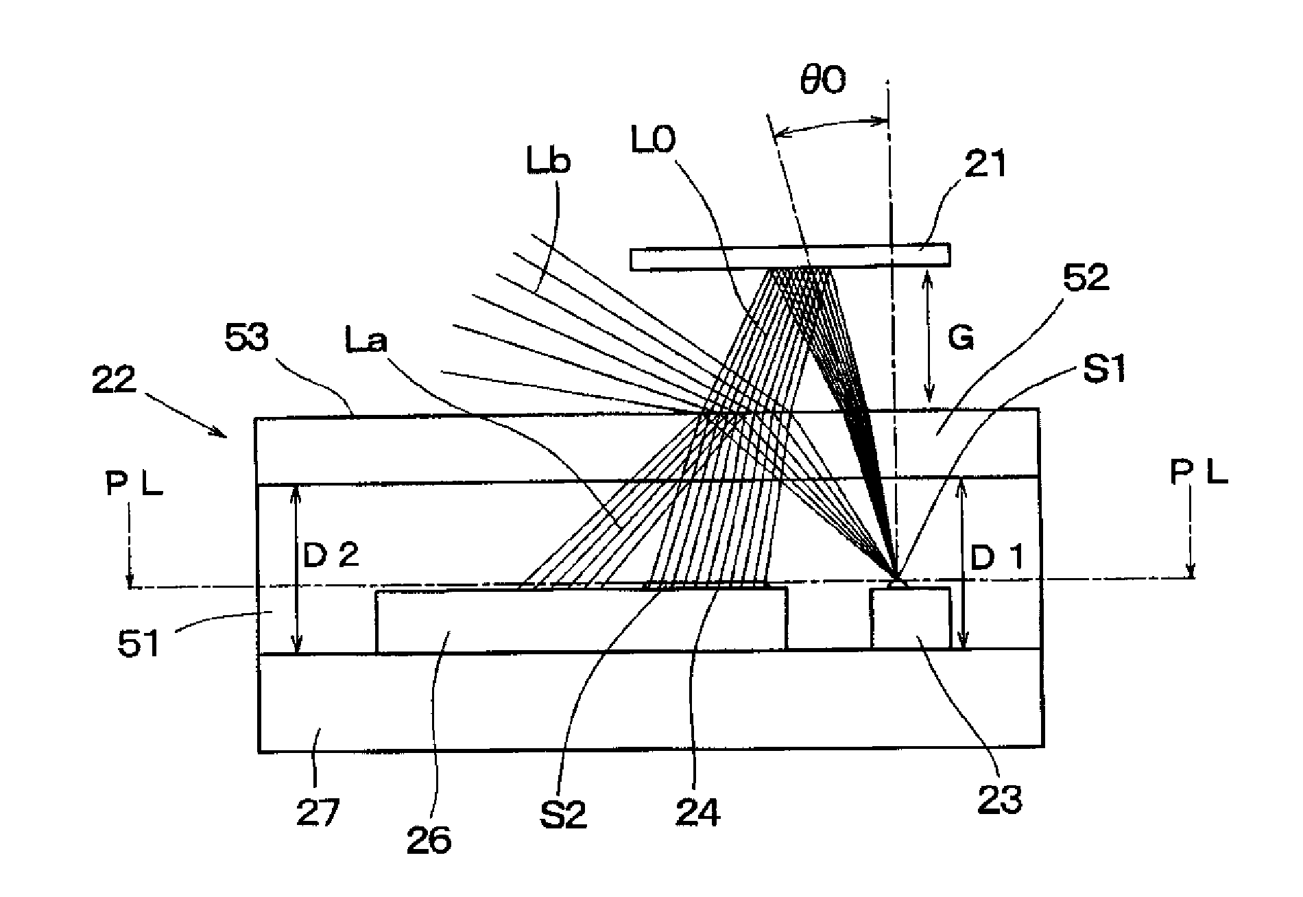
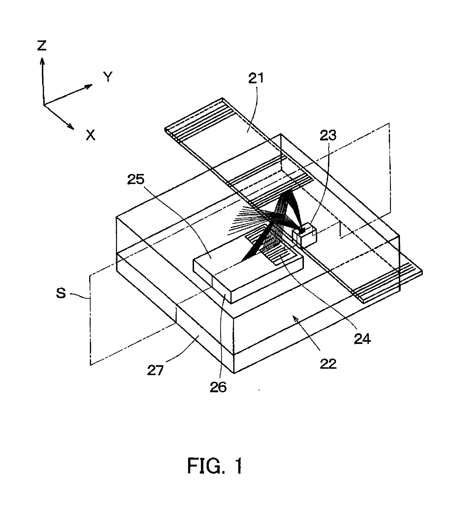
[0058]FIG. 1 is a schematic diagram showing the configuration of a reflective encoder of Embodiment 1. A reflective scale 21 having stripes at regular intervals formed thereon is fixed to a moving object to be measured (hereinafter, the object to be measured is merely referred to as the object) and is movable in the direction of an X axis corresponding to the direction in which the stripes are arranged. A detection head 22 which is a reflective sensor is placed opposite to the reflective scale 21.

[0059]The detection head 22 is formed of a light-emitting element 23 realized by a LED chip, a light-receiving element 24 having a photodiode array as a light-receiving portion, a semiconductor device realized by a photo-IC chip 26 including a signal processing circuit part 25, and a substrate 27 on which the abovementioned components are mounted.

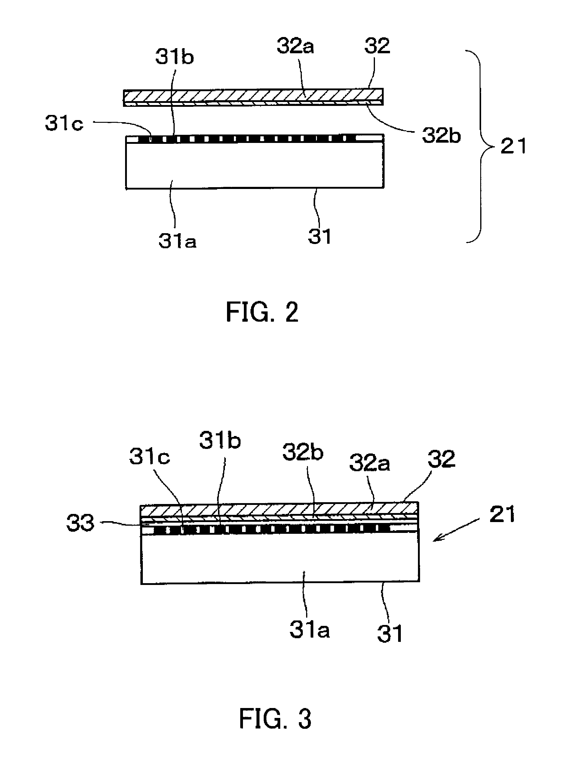
[0060]As shown in FIG. 2, the reflective scale 21 is formed of a pattern-forming sheet 31 and a reflective-layer-forming sheet 32. The pattern-for...

embodiment 2

[0105]FIG. 15 is a section view showing a simulation model of a reflective sensor that is Embodiment 2 of the present invention. In this embodiment, the members identical to those described in Embodiment 1 are designated with the same reference numerals. This is also applied to the later-described Embodiments 3 to 5.

[0106]In this reflective sensor, the height of the interface 53 is increased and the radius Rmax of the annular high-illuminance region produced by the totally reflected light is increased as compared with Embodiment 1. Specifically, D1 and D2 are set to 0.90 mm, Ni to 1.54 (epoxy resin), and No to 1.00 (air). From those values, Ri is nearly equal to 1.45 mm.

[0107]As a result, as shown in the illuminance distribution chart of FIG. 16, the size of an allowable circle in which the light-receiving portion can be placed is increased, and the area of the light-receiving region S2 of the light-receiving element 24 can be increased as compared with Embodiment 1. For example, in...

embodiment 3

[0108]FIG. 17 is a section view showing a simulation model of a reflective sensor that is Embodiment 3 of the present invention. In this embodiment, as for the height of the interface 53, the height D1 on the light-emitting-element side and the height D2 on the light-receiving-element side have different values. Specifically, D1 is set to 0.3 mm, D2 to 0.7 mm, Ni to 1.54 (epoxy resin), and No to 1.00 (air). From those values, Ri is nearly equal to 0.85 mm.

[0109]In Embodiment 3, the light-emitting element 23 is covered 0.3 mm above with the light-transmissive sealing resin 51 and the transparent glass 52. A cylindrical concave portion with an inner diameter of 0.6 mm and a depth of 0.4 mm is formed in the upper part of the transparent glass 52.

[0110]FIG. 18 shows optical paths of the effective reflected light and the totally reflected light in the package in Embodiment 3. The light-receiving region S2 is placed at a position where the totally reflected light does not enter.

[0111]As s...


PUM


Abstract

A reflective sensor is disclosed which prevents divergent light from a light source from being totally reflected by an interface between the package and the outside thereof and entering a light-receiving element without using a light-shield means and which allows an improved S / N ratio and reduced variations in performance. The reflective sensor includes a light-emitting element and a light-receiving element which are provided on a surface, and a light-transmissive member which covers the light-emitting element and the light-receiving element. The light-receiving element includes a light-receiving region which is spaced from the light-emitting element along the surface, and which light-receiving region is closer to the light-emitting element than an area on the surface that would be illuminated by unimpeded light rays which are totally reflected by an interface between the light-transmissive member and the outside thereof and are directed toward the light-receiving element.

Description

BACKGROUND OF THE INVENTION[0001]The present invention relates to a reflective sensor which projects light emitted from a light-emitting element onto an object to be measured, receives the light reflected thereby at a light-receiving element, and detects displacement of the object on the basis of a change in the amount of the received light.[0002]FIG. 23 is a perspective view showing a reflective encoder in the related art. FIG. 24 shows an XZ section thereof. FIG. 25 shows a YZ section orthogonal to a displacement detection axis corresponding to an X axis. Light rays are radiated from a light-emitting element 1 formed of an LED chip, and some of the light is reflected by a reflective scale 2 and is received by a light-receiving element 3 formed of a photo-IC chip containing a signal processing circuit. The light-emitting element 1 and the light-receiving element 3, each of which is a semiconductor device, are die-bonded to a printed circuit substrate 4 and covered with transparent ...

Claims


Application Information

Patent Timeline
Patent Type & Authority Applications(United States)
IPC IPC(8): G01B11/14
CPCG01D5/34H01L25/167H01L33/60H01L2224/48465H01L2924/3025H01L2224/48091H01L2924/00014H01L2924/00
Inventor IGAKI, MASAHIKOATSUTA, AKIO
Owner CANON KK
Why Eureka
Try Eureka