Direct engraving of flexographic printing plates

US20080018943A1Inactive Publication Date: 2008-01-24EASTMAN KODAK CO

Image

  • Direct engraving of flexographic printing plates
  • Direct engraving of flexographic printing plates
  • Direct engraving of flexographic printing plates

Examples


Embodiment Construction

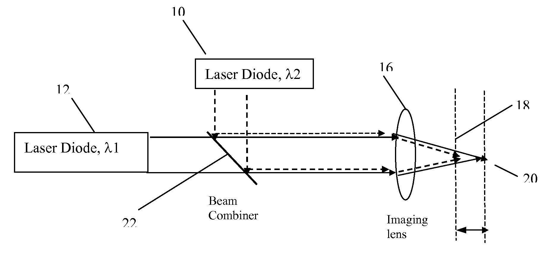
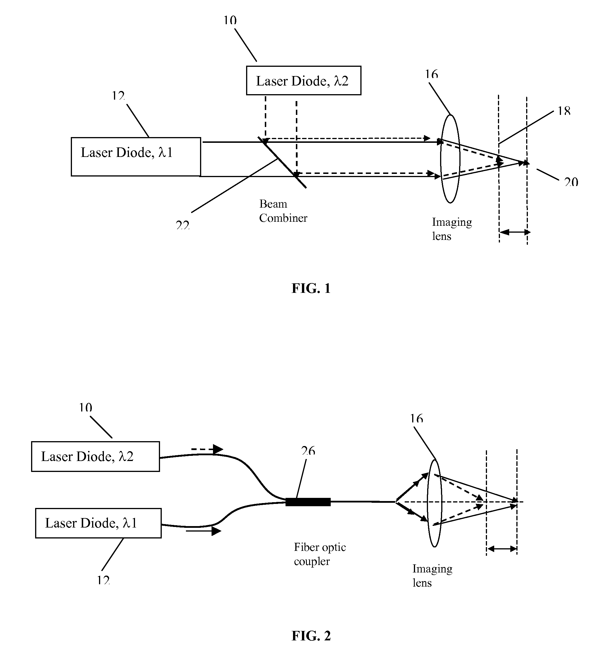
[0035]The present invention suggests several methods by which the laser diode light is controlled in order to enhance the direct engraving and ablating effect. Referring to FIG. 1, the invention is described by the schemes shown for the specific case of two laser diodes 10, 12 that emit in two different wavelengths. By using laser diodes which emit at different wavelengths, and by controlling the dispersion of the imaging lens 16, the focus points 18, 20 at the different wavelengths will be shifted one relative to each other.

[0036]FIG. 2 describes the same idea as FIG. 1 for the case of fiber coupled diodes. The two different wavelengths are combined into one fiber using a fiber optic coupler 26 instead of the beam combiner 22.

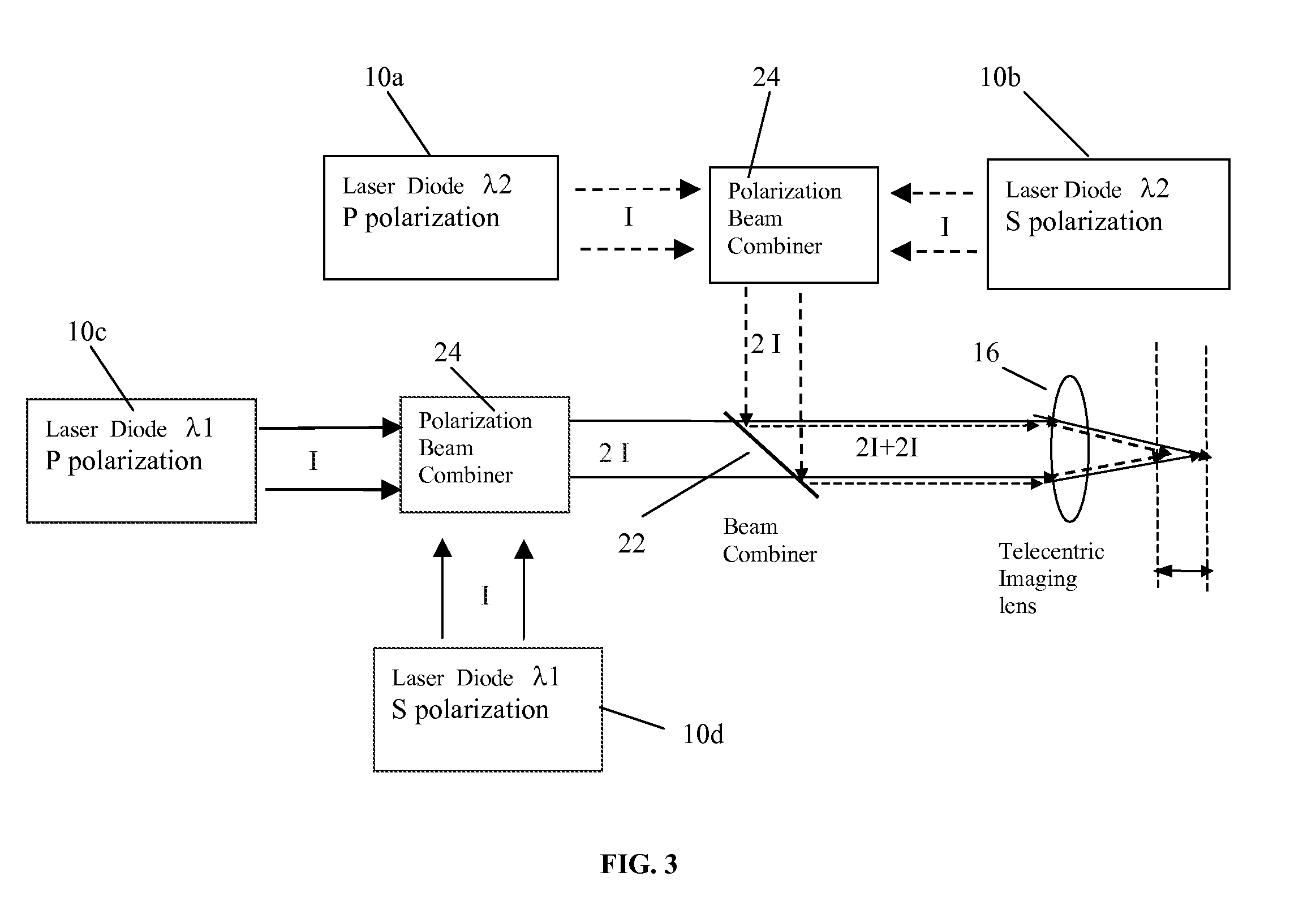
[0037]The light emitted from laser diodes is highly polarized. Therefore, by using a polarization beam combiner 24, shown in FIG. 3, the power of two diodes that emit the same wavelength 10a, 10b can be combined into one path. Doing so the power of each wavele...


PUM

PropertyMeasurementUnit
Thicknessaaaaaaaaaa
Diameteraaaaaaaaaa
Depthaaaaaaaaaa

Abstract

An optical imaging head for direct engraving of flexographic printing plates, comprising at least two laser diodes (10, 12) emitting radiation in one or more wavelengths; and means for imaging the one or more wavelengths of radiation at different depths relative to a surface of the plate.

Description

CROSS REFERENCE TO RELATED APPLICATIONS[0001]Reference is made to commonly-assigned copending U.S. patent application Ser. No. 11 / 353,217, filed Feb. 13, 2006, entitled FLEXOGRAPHIC PRINTING PLATE PRECURSOR AND IMAGING METHOD, by Kimelblat et al., the disclosure of which is incorporated herein.FIELD OF THE INVENTION[0002]This invention relates to an optical printing head and methods for direct engraving of sensitive flexographic printing plates by utilizing high power diode lasers.BACKGROUND OF THE INVENTION[0003]Traditional flexographic printing methods prepare a printing plate by molding an elastomer such as rubber in a mold, or by photo-polymerizing a UV sensitive polymer. These methods are slow and expensive.[0004]Another technique for creating a raised pattern on an elastomer surface is to directly cut the raised pattern using the well known NdYAG or CO2 lasers, which are currently used as light sources in the direct engraving printing systems. The laser is controlled to ablate...

Claims


Application Information

Patent Timeline
24 Jan 2008
Publication
US20080018943A1
IPC
B41C1/04
CPC
B23K26/0608; B41C1/05; B23K26/0648; B23K26/0617
Inventors
EYAL, OPHIR; LIBERMAN, MOSHE