Lens blank and lens elements as well as method for their production

a technology of lens elements and blanks, applied in the field of lens blanks and lens elements as well as their production methods, can solve the problems of unfavorable manner, precise effect of strain shift, and cannot be clarified by means of experiments or elaborate simulations, and achieve favorable strain distribution and reduce waste

Active Publication Date: 2008-01-24
CARL ZEISS SMT GMBH
View PDF4 Cites 2 Cited by
  • Summary
  • Abstract
  • Description
  • Claims
  • Application Information

AI Technical Summary

Benefits of technology

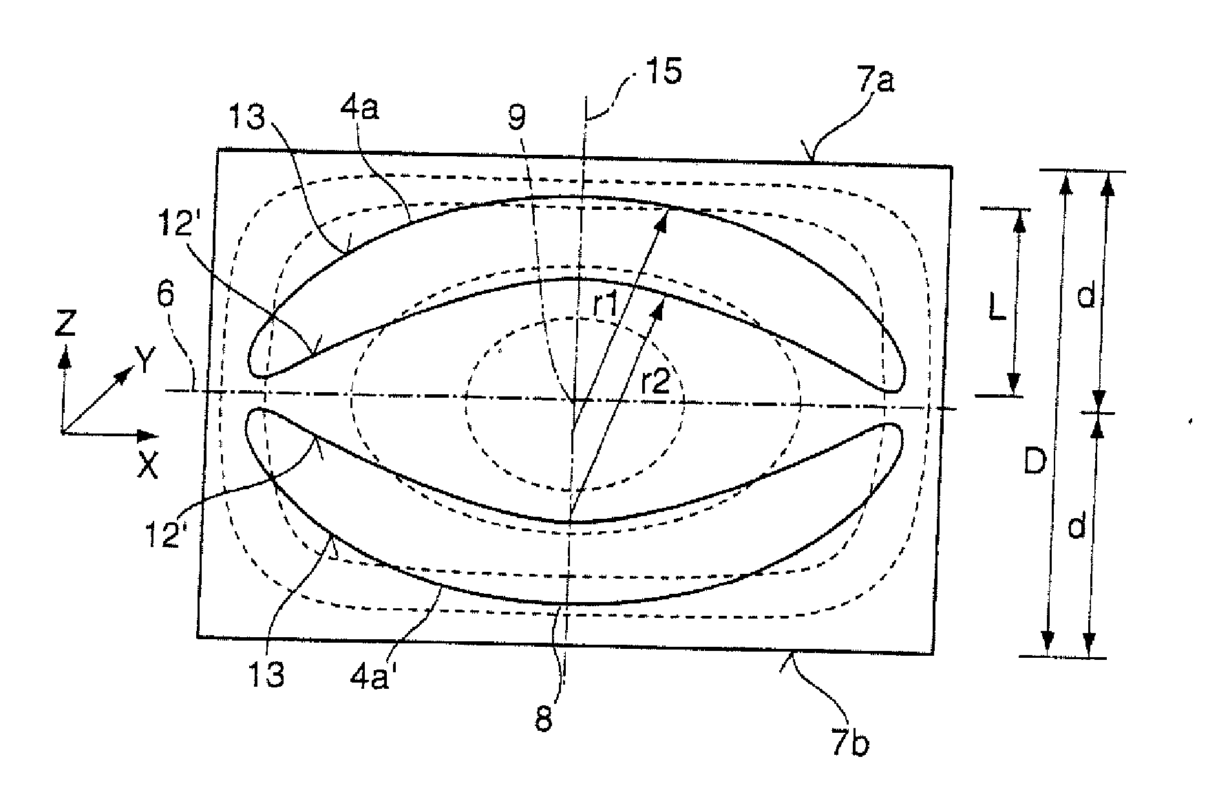
[0025] By manufacturing two or more lens elements from the tempered blank, cutting waste is reduced. In this process the tempered blank can, for example, be divided along the mid-plane into two partial regions of the same size, from which partial regions in each case identically formed lens elements are produced so that in order to manufacture two blanks by means of the method according to the invention the volume required is identical to the volume that is required according to the method known from prior art in order to manufacture two lens elements from two blanks that have been tempered separately. From the tempered blank it is also possible to produce two lens elements that are differently formed; in this case the tempered blank can be divided asymmetrically, but again in such a manner that a favorable strain distribution is achieved in each lens element. This is of advantage in particular if one of the lens elements already requires a height of the blank of >80 mm, because the production of blanks with thicknesses exceeding 100-120 mm is associated with problems in relation to production technology (handling, maximum machine capacity, tempering programs etc.).
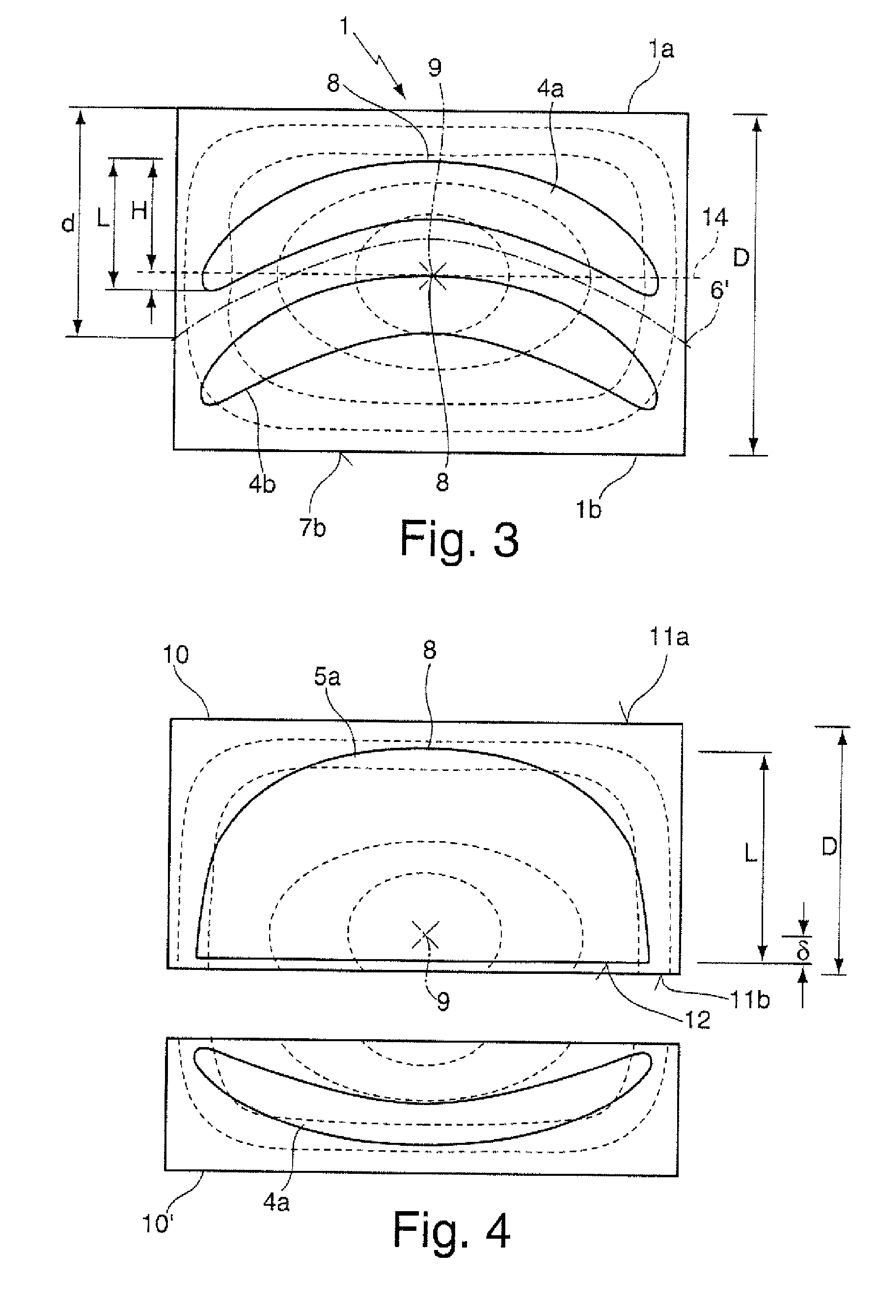
[0026] In a particularly preferred variant the tempered blank is cylindrical, with dividing taking place along a plane cut-surface that is essentially aligned at a right angle in relation to the cylinder axis, or along a spherical cut-surface. In this case dividing can take place by using normal cutting tools, wherein the use of spherical cut-surfaces is associated with an advantage in that the existing volume of the blanks can be better utilized,

Problems solved by technology

A body with high density gradients that are oriented differently, which body is formed by the lens elements 4, 5, thus behaves in an unfavorable manner in the sense that the shift in strain can be calculated in advance only with considerable difficulty and in that the precise effect of such shift in strain can only be clarified by means of experiments or by means of elaborate simulation.
If asymmetrical lens elements are cut from tempered blanks in a manner described in FIG. 5b and FIG. 5c, the unfavorable effects described above thus occur, namely on the one hand a high SBR observed in the edge regions of the lens elements, and on the other hand a shift in the strain after cutting the lens elements, which shift results in a shift of the SBR,

Method used


Image

  • Lens blank and lens elements as well as method for their production
  • Lens blank and lens elements as well as method for their production
  • Lens blank and lens elements as well as method for their production

Examples


Embodiment Construction

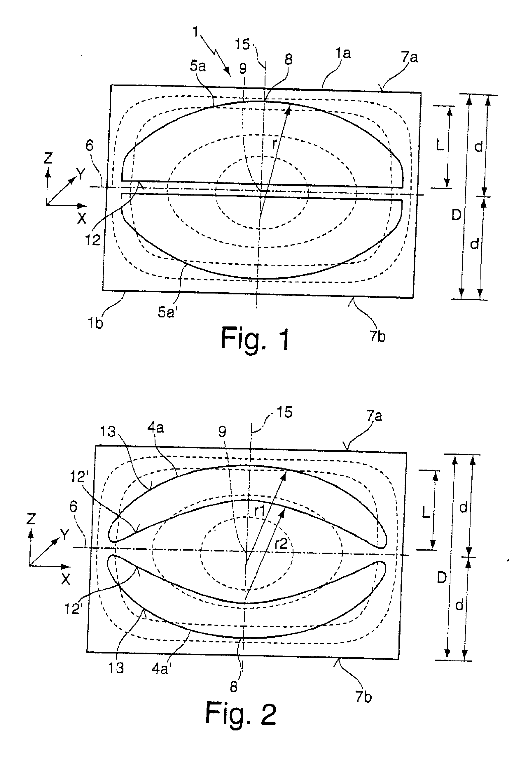
[0067]FIG. 1 shows a section of a tempered cylindrical blank 1 which comprises a thickness D of 10 cm between a first and a second end face 7a, 7b, with the density distribution of said blank 1 essentially corresponding to the density distribution shown in FIG. 5. In this arrangement the cylindrical blank 1 and thus the density distribution are rotationally symmetrical in relation to a longitudinal axis 15 that extends in z-direction. The density is at its maximum in the center, ire at the point of intersection between a mid-plane 6 of the tempered blank 1 and the longitudinal axis 15; this is also where the strain birefringence of the tempered blank 1 is at its minimum 9.

[0068] In order to manufacture two plano-convex lens elements 5a, 5a′ the tempered blank is divided, along the mid-plane 6 that serves as a cutting plane, into a first partial volume 1a and a second partial volume 1b, which partial volumes comprise an identical thickness d of somewhat more than 5 cm. The two plano...


PUM

PropertyMeasurementUnit
thicknessaaaaaaaaaa
thicknessaaaaaaaaaa
thicknessaaaaaaaaaa

Abstract

A method for manufacturing a preferably asymmetrical lens element (5a) from a tempered blank (1) is characterized by: producing the lens element (5a) from a first partial volume (1a) of the tempered blank (1), whose thickness d is less than approximately 70%, preferably less than approximately 60%, particularly preferably less than approximately 50% of the thickness D of the tempered blank (1). Preferably, from a second partial volume (1b) of the tempered blank (1) at least a further lens element (5a′) is produced, wherein before the lens elements (5a, 5a′) are produced the tempered blank (1) is divided into the first and second partial volume (1a, 1b).

Description

CROSS-REFERENCE TO RELATED APPLICATIONS [0001] This application claims priority under 35 U.S.C. §119(a) to German Patent Application No. 10 2006 031 995.8, filed on Jul. 11, 2006, the entire contents of which are hereby incorporated by reference. BACKGROUND OF THE INVENTION [0002] The invention relates to a method for producing a preferably asymmetrical lens element from a tempered blank; to a lens blank for microlithography, preferably with cylindrical geometry; as well as to lens elements and to a projection lens with such a lens element. [0003] Lens elements made of fused silica are, for example, used in projection exposure apparatuses for microlithography. In such apparatuses, radiation generated by a usually pulsed laser at an operating wavelength of e.g. 248 nm (KrF laser) or 193 nm (ArF laser) is imaged to a sharply delimited very homogeneously illuminated image field by means of an illumination system, in which image field a mask is arranged. A pattern that is provided on th...

Claims


Application Information

Patent Timeline
Patent Type & Authority Applications(United States)
IPC IPC(8): G02B13/14G02B3/00
CPCG02B1/02G03F7/70341G02B3/06G02B1/08
Inventor EVA, ERIC
Owner CARL ZEISS SMT GMBH
Why Eureka
Try Eureka