Magnetic head

Inactive Publication Date: 2008-01-24
TOSHIBA STORAGE DEVICE CORP
View PDF11 Cites 20 Cited by
  • Summary
  • Abstract
  • Description
  • Claims
  • Application Information

AI Technical Summary

Benefits of technology

[0019]According to the present invention, in the write coil facing area facing the area in which the thin-film coil pattern of the write coil is disposed, the heater coil which causes the medium facing surface is to protrude toward the recording medium side by thermal expansion by power distribution and overheating is disposed via the insulating layer. Thus, the heater pattern which generates heat the most in the heater is disposed in the vicinity of the write coil so as to face the write coil, the heat caused by the power distribution to the heater is efficiently transmitted to the write coil so as to thermally expand the write coil, and the thermal expansion of the write coil causes the medium facing surface of the head to efficiently protrude toward the medium side, thereby controlling the clearance of the write element (magnetic flux emitting unit by write gap) or the read element. Moreover, since the heat of the heater coil is transmitted and dissipated through the wri

Problems solved by technology

However, there are problems that collision with minute protrusions on the magnetic disk surface readily occur when the flying height of the magnetic head is reduced, and variations in the clearance of heads are present in the range of common differences of mechanisms; therefore, when contact with the medium is taken into consideration, flying heights smaller than the common differences cannot be set.
However, in conventional heater-built-in magnetic heads, what kind of disposition of a heater coil enhances the heater efficiency has not been satisfactorily ment

Method used


Image

  • Magnetic head
  • Magnetic head
  • Magnetic head

Examples


Embodiment Construction

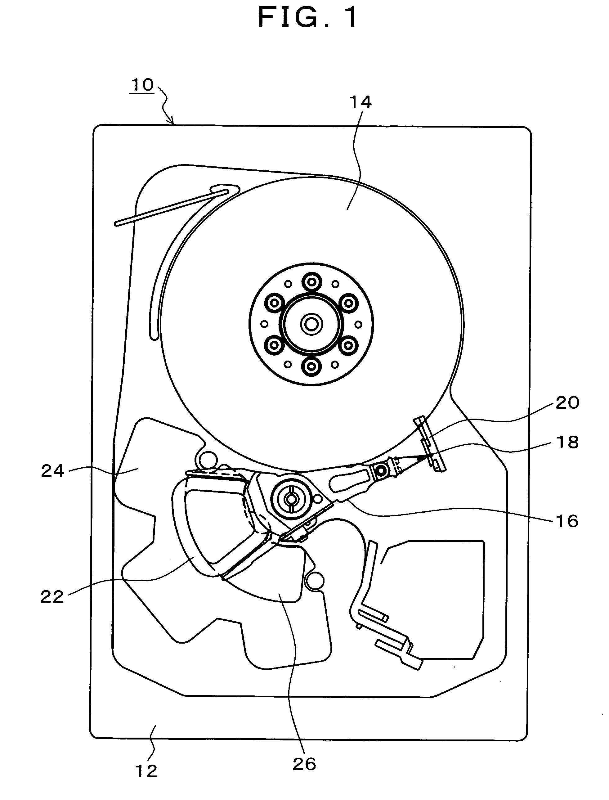
[0039]FIG. 1 is an explanatory drawing of a magnetic disk apparatus in which a magnetic head of the present invention is used. In FIG. 1, a magnetic disk 10 shows a structure in a chassis base 12 with a chassis cover removed, a magnetic disk 14 which is rotated at a constant speed by a spindle motor is provided in the chassis base 12, and a rotary actuator 16 is turnably disposed for the magnetic disk 14 by a shaft unit 15. The rotary actuator 16 supports a magnetic head 18 according to the present invention at the distal end thereof, and a coil 22 is disposed at the rear thereof. The coil 22 is turnable along a magnet 26 on a lower yoke 24 which is fixed to the chassis base 12, and an unillustrated upper yoke having the same shape as the lower yoke 24 is disposed in the upper side of the coil 22; however, in the present embodiment, they are shown in the state that the upper yoke is removed. A magnetic circuit unit is formed by the lower yoke 24, the magnet 26, and the upper yoke (n...


PUM


Abstract

A magnetic head is composed of a write head which magnetically records information by emitting magnetic flux, which is generated by a write coil, from a magnetic pole unit to a recording medium; and a read head having a reading element which converts record magnetic flux, which is emitted from the recording medium, to an electric signal. In a write coil facing area facing an area in which the thin-film coil pattern of the write coil is disposed, a heater coil which causes a medium facing surface to protrude toward a recording medium side by thermal expansion caused by power distribution and overheating is disposed via an insulating layer. In the heater coil, a wide terminal pattern is disposed outside the write coil facing area, and a heater pattern having a width narrower than the terminal pattern is disposed in the write coil facing area.

Description

[0001]This application is a priority based on prior application No. JP 2006-1979384, filed Jul. 20, 2006, in Japan.BACKGROUND OF THE INVENTION[0002]1. Field of the Invention[0003]The present invention relates to a magnetic head which is caused to fly over a rotating recording medium and read / write data, and particularly relates to a magnetic head which can control the clearance between a head and a recording medium by changing the protruding distance of a medium facing surface by thermal expansion caused by power distribution to and heating of a heater.[0004]2. Description of the Related Arts[0005]Conventionally, the flying height of a magnetic head with respect to a recording surface of a magnetic disk has to be reduced in order to realize a high recording density of a magnetic disk apparatus; and, recently, flying heights of 10 nm order have been realized. However, there are problems that collision with minute protrusions on the magnetic disk surface readily occur when the flying ...

Claims


Application Information

Patent Timeline
IPC IPC(8): G11B5/127
CPCG11B5/17G11B5/314G11B5/6064G11B5/6011G11B5/3967G11B5/127G11B5/31G11B5/60
Inventor AOKI, KENICHIRO
Owner TOSHIBA STORAGE DEVICE CORP
Why Eureka
Try Eureka