Piezoelectric Speaker and Method for Manufacturing the Same

a technology of piezoelectric speaker and manufacturing method, which is applied in the direction of piezoelectric/electrostrictive transducer, diaphragm construction, transducer type, etc., can solve the problems of limited diameter and thickness, difficult to increase the size of the casing and the speaker against the trend, and the device having a plurality of sizes, etc., to achieve convenient and convenient mounting and mounting. the effect of volumetric capacity and convenient mounting

Active Publication Date: 2008-01-24
PANASONIC CORP
View PDF7 Cites 13 Cited by
  • Summary
  • Abstract
  • Description
  • Claims
  • Application Information

AI Technical Summary

Benefits of technology

[0031] According to the first aspect, the connecting components connected to at least two diaphragms are displaced in phase with the at least two diaphragms at low-frequency reproduction, and therefore the connecting components each functions as a diaphragm. Thus, the piezoelectric speaker, having a preferable sound pressure characteristic at low-frequencies, capable of performing stereo reproduction can be mounted in a space of a reduced mounting volumetric capacity.
[0032] According to the second aspect, separate voltages can be applied to both poles of each of the piezoelectric elements mounted on the diaphragms through the first dampers and the second dampers.
[0033] According to the third aspect, the skin layers of one piece of laminated material are processed so as to form the respective components of the piezoelectric speaker, thereby simplifying the manufacture thereof.
[0034] According to the fourth aspect, the skin layers are etched and removed at corresponding positions on the front side and the back side so as to form the insulating slits and the connecting components, thereby simplifying the manufacture thereof.
[0035] According to the fifth aspect, the connecting components are formed by the same core layer as used for other components, thereby simplifying the manufacture thereof.
[0036] According to the sixth aspect, only a voltage applied from the first dampers can be applied to the adhering surface of each of the piezoelectric elements mounted on the diaphragms.

Problems solved by technology

However, when the speaker unit is mounted on a compact device or the like, the speaker unit is required to have a restricted diameter and thickness depending on a volumetric capacity of a casing of the device and other devices to be mounted thereon.
However, it is difficult to increase the sizes of the casing and the speaker against the trend or to leave the size of the device having a plurality of speaker units mounted thereon unchanged from a current size.
Under such circumstances, although the high quality sound reproduction is expected, the compact device has mounted thereon an electrodynamic small-diameter micro speaker which provides a poor low-frequency reproduction performance.

Method used


Image

  • Piezoelectric Speaker and Method for Manufacturing the Same
  • Piezoelectric Speaker and Method for Manufacturing the Same
  • Piezoelectric Speaker and Method for Manufacturing the Same

Examples


first embodiment

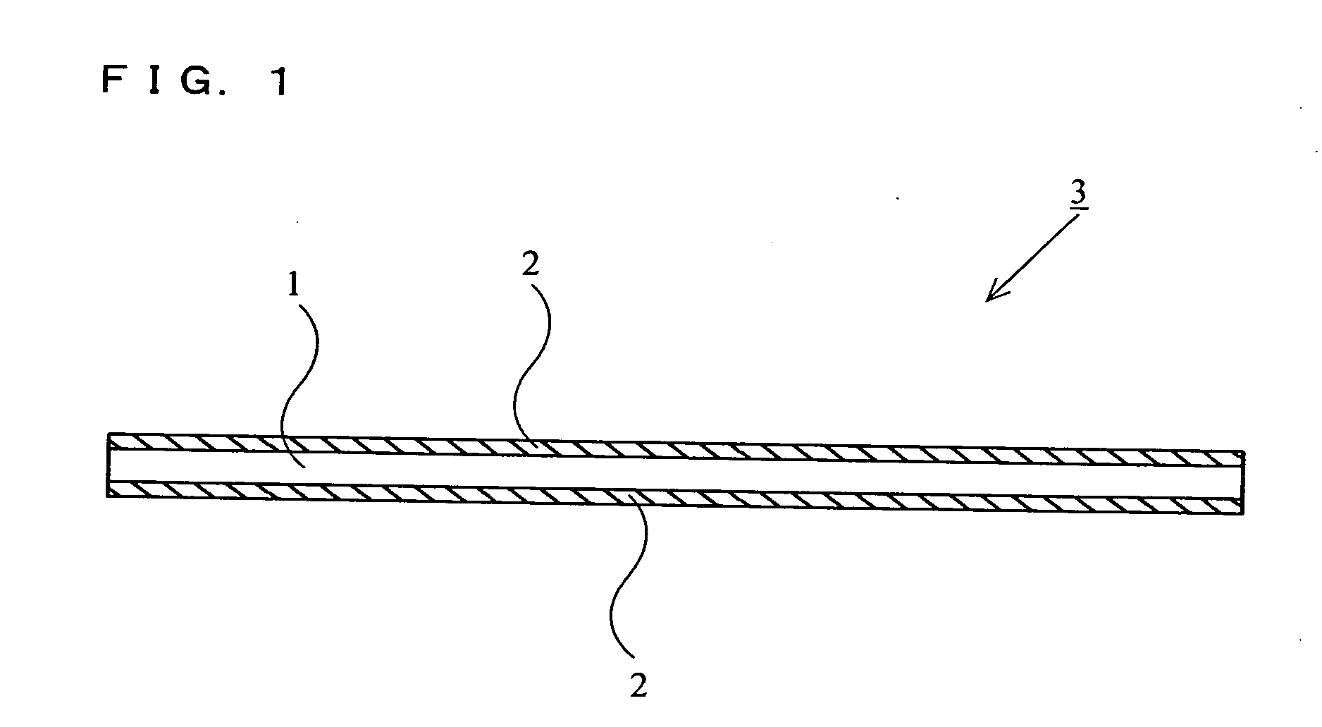
[0095] Hereinafter, a piezoelectric speaker according to a first embodiment of the present invention will be described with reference to the drawings. FIG. 1 is a diagram illustrating a cross-sectional structure of a speaker diaphragm for use in the piezoelectric speaker.

[0096] The diaphragm according to the present embodiment has a laminated material 3. The laminated material 3, including a core layer 1 and skin layers 2, is laminated such that the core layer 1 corresponding to an intermediate layer is sandwiched from both surfaces thereof between the skin layers 2. The core layer 1 is made of insulating material. The skin layers 2 are made of conductive material.

[0097] For example, while the insulating material of the core layer 1 is polyimide, the insulating material thereof may be polyimide metamorphic body. Further, the insulating material of the core layer 1 may be material having insulating properties such as rubber high polymer material (SBR, NBR, acrylonitrile and the lik...

second embodiment

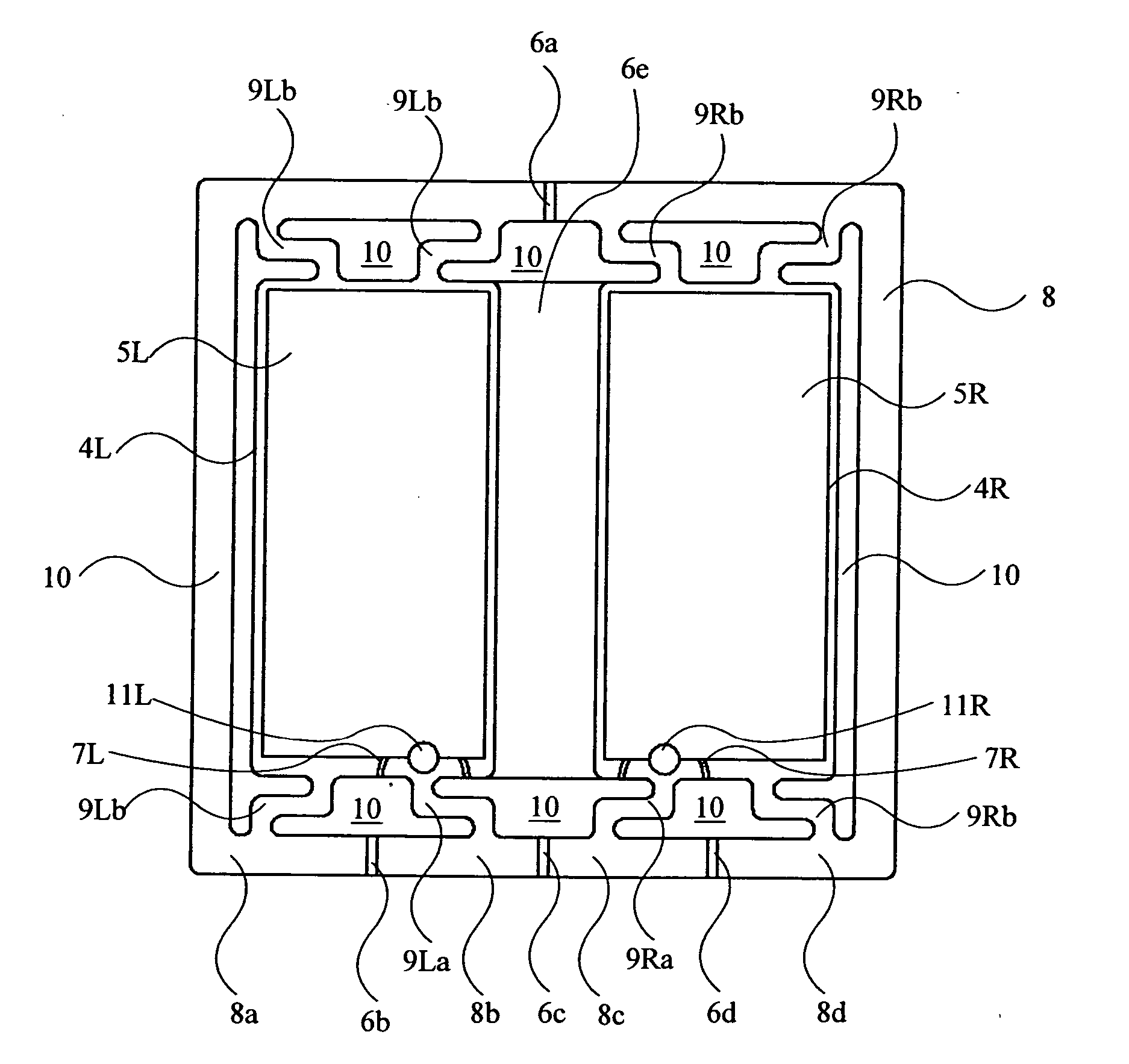
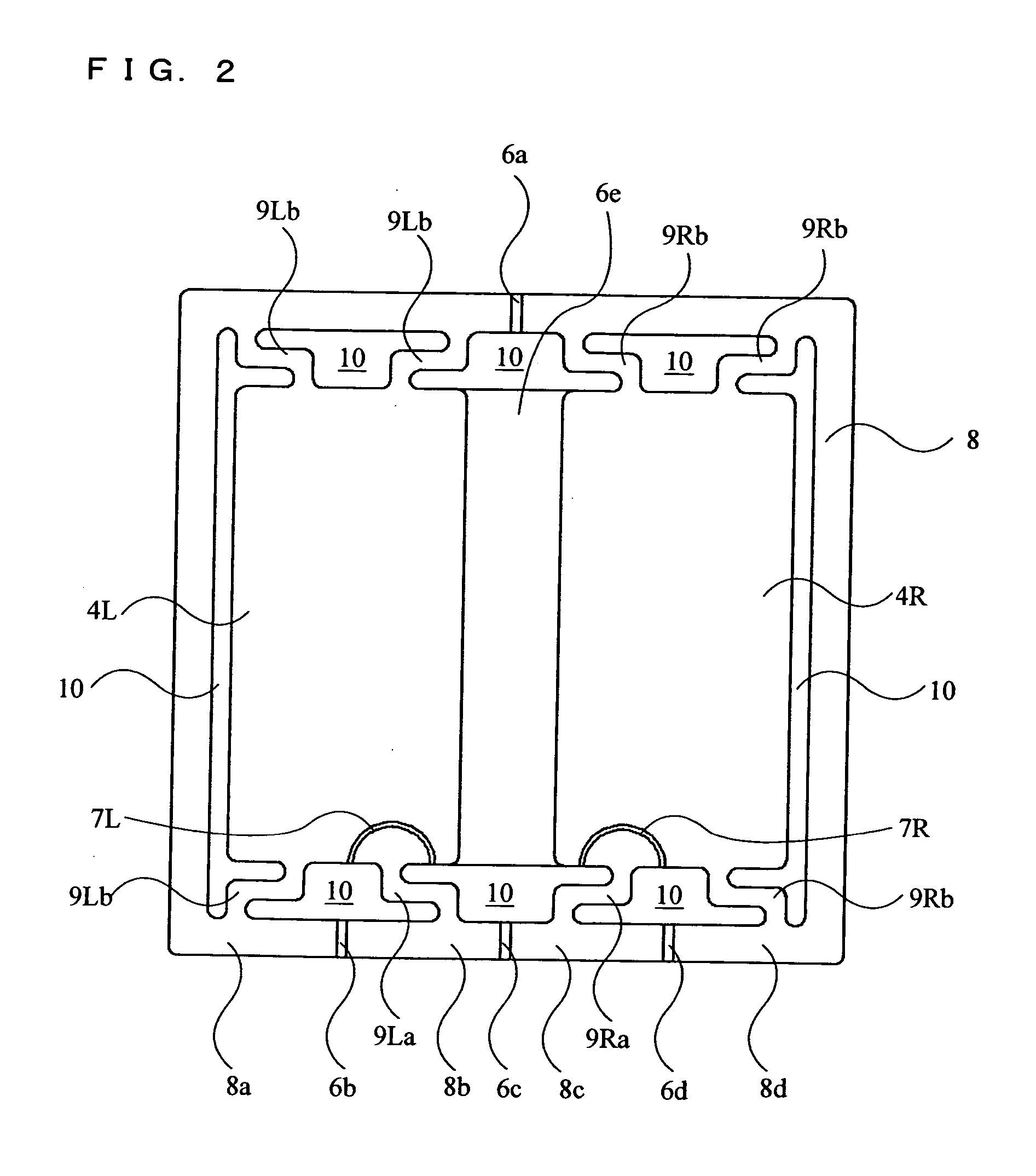
[0129] Hereinafter, a piezoelectric speaker according to a second embodiment of the present invention will be described with reference to the drawings. FIG. 11 is a diagram illustrating a front surface of the piezoelectric speaker which does not have a piezoelectric element 25 mounted thereon. FIG. 12 is a diagram illustrating the front surface of the piezoelectric speaker which has the piezoelectric element 25 mounted thereon. The front side and the back side of the piezoelectric speaker have the same structure, and therefore the structure of the front side (front surface) will be mainly described. A cross-sectional structure of a speaker diaphragm for use in the piezoelectric speaker is the same as the structure described for the first embodiment with reference to FIG. 1, and therefore a detailed description thereof is not given.

[0130] As shown in FIG. 11 and FIG. 12, the piezoelectric speaker according to the second embodiment has four diaphragms, which are formed by separating ...

third embodiment

[0153] Hereinafter, a piezoelectric speaker according to a third embodiment of the present invention will be described with reference to the drawings. FIG. 16 is a diagram illustrating a front surface of the piezoelectric speaker which does not have the piezoelectric element 5 mounted thereon. FIG. 17 is a cross-sectional view illustrating a structure of a section AA of the piezoelectric speaker shown in FIG. 16. FIG. 18 is a diagram illustrating the front surface of the piezoelectric speaker which have the piezoelectric element 5 mounted thereon. The front side and the back side of the piezoelectric speaker has the same structure, and therefore the structure of the front side (front surface) will be mainly described. In FIG. 17, an enlarged scale is used for a thickness direction so as to clearly illustrate structures of the frame 8, an external diaphragm 61, and an external frame 60, and a positional relationship thereamong.

[0154] A fundamental structure (a structure of the centr...


PUM

PropertyMeasurementUnit
total thicknessaaaaaaaaaa

Abstract

A piezoelectric speaker comprises a plurality of diaphragms, connecting components, and piezoelectric elements. The plurality of diaphragms are each formed by a laminated material in which a core layer made of an insulating material is laminated to skin layers each made of a conductive material so as to form the skin layers on both surfaces of the core layer. The connecting components each corresponds to a plate-shaped component of the insulating material and connects between at least two of the plurality of diaphragms. Piezoelectric elements are mounted on surfaces of the plurality of diaphragms, respectively. The plurality of diaphragms are insulated from each other such that separate voltages are applied to the piezoelectric elements mounted thereon, respectively.

Description

TECHNICAL FIELD [0001] The present invention relates to a piezoelectric speaker for use in an acoustic device and the like, and a method for manufacturing the same. BACKGROUND ART [0002] Conventionally, a piezoelectric speaker, known as a compact and low-current driven acoustic device in which a piezoelectric material is used as an electro-acoustic transducer element, is used as an acoustic output device for use in a compact device (for example, see Patent Document 1). In general, the piezoelectric speaker has a structure in which a piezoelectric element having formed thereon an electrode of silver thin film or the like is adhered to a metal diaphragm. A sound output mechanism of the piezoelectric speaker is such that an application of an AC voltage to both surfaces of the piezoelectric element causes a generation of a shape distortion of the piezoelectric element, so that the metal diaphragm is vibrated, thereby generating a sound. [0003] On the other hand, a low-frequency reproduc...

Claims


Application Information

Patent Timeline
Patent Type & Authority Applications(United States)
IPC IPC(8): H04R17/00H01L41/22H04R1/40H04R7/02H04R7/08H04R31/00
CPCH04R7/10H04R17/00H04R31/006Y10T29/42H04R2307/029H04R2499/11H04R2307/027
Inventor OGURA, TAKASHIMURATA, KOUSAKU
Owner PANASONIC CORP
Why Eureka
Try Eureka