Hydrocarbon recovery in the fischer-tropsch process

Inactive Publication Date: 2008-01-24
REG SYNTHETIC FUELS LLC
View PDF12 Cites 28 Cited by
  • Summary
  • Abstract
  • Description
  • Claims
  • Application Information

AI Technical Summary

Benefits of technology

[0008]Embodiments of the invention provide a separation system which combines heat and mass transfer

Problems solved by technology

Unfortunately, there are few economically attractive methods for recovering these heavy ends from the tail gas.
However, conventional lean oil recovery methods require a

Method used


Image

  • Hydrocarbon recovery in the fischer-tropsch process
  • Hydrocarbon recovery in the fischer-tropsch process
  • Hydrocarbon recovery in the fischer-tropsch process

Examples


Embodiment Construction

[0013]Unless otherwise specified, all quantities, percentages and ratios herein are by weight.

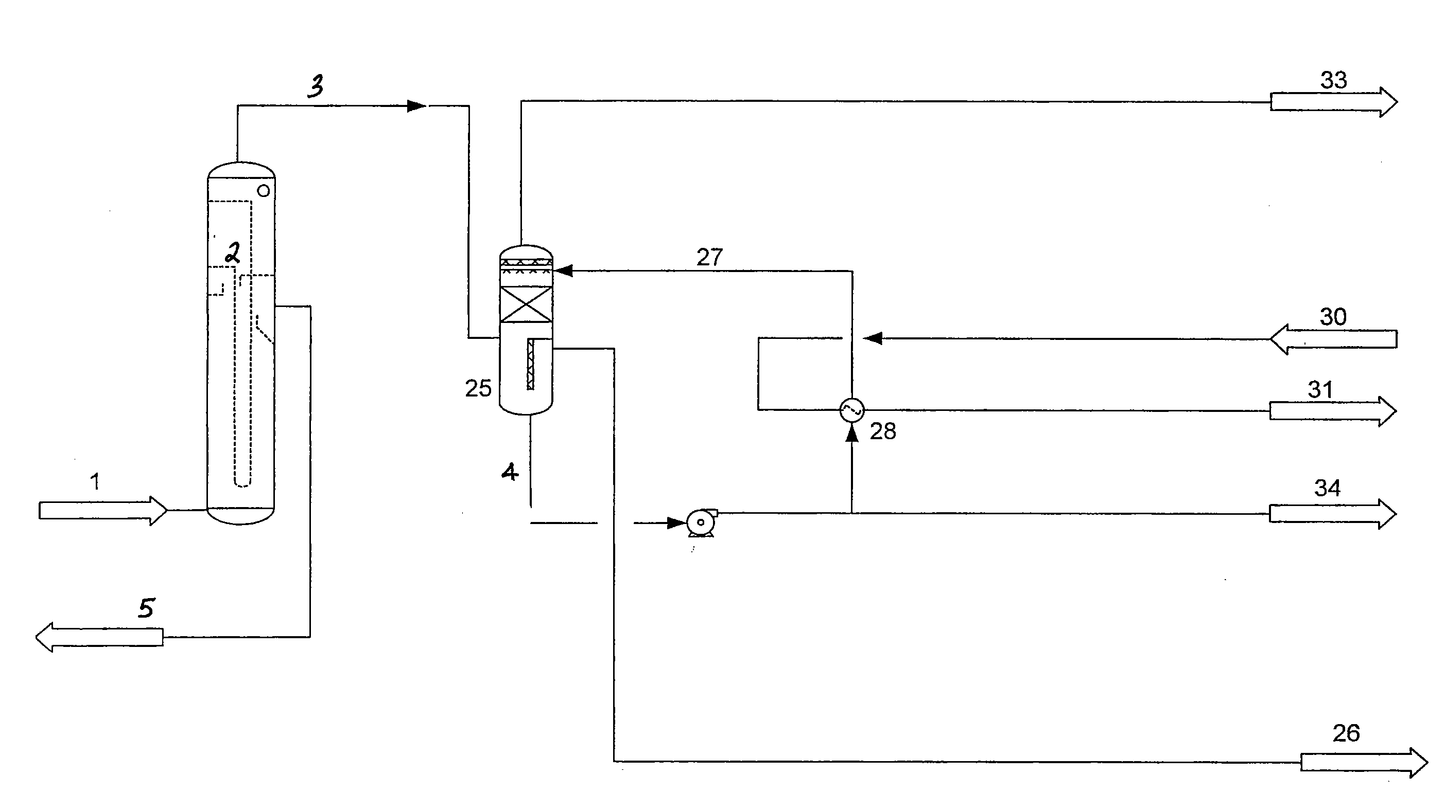
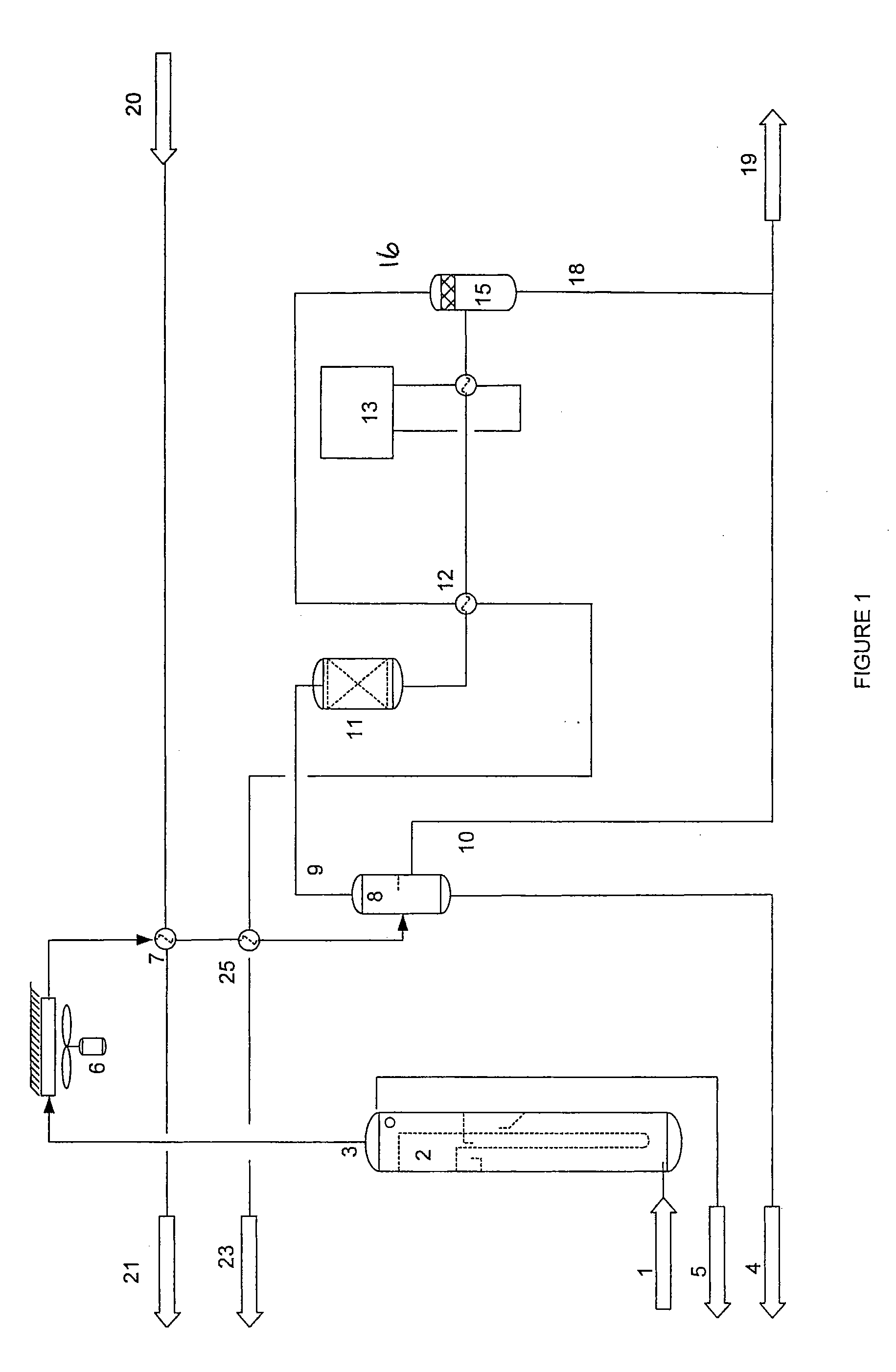
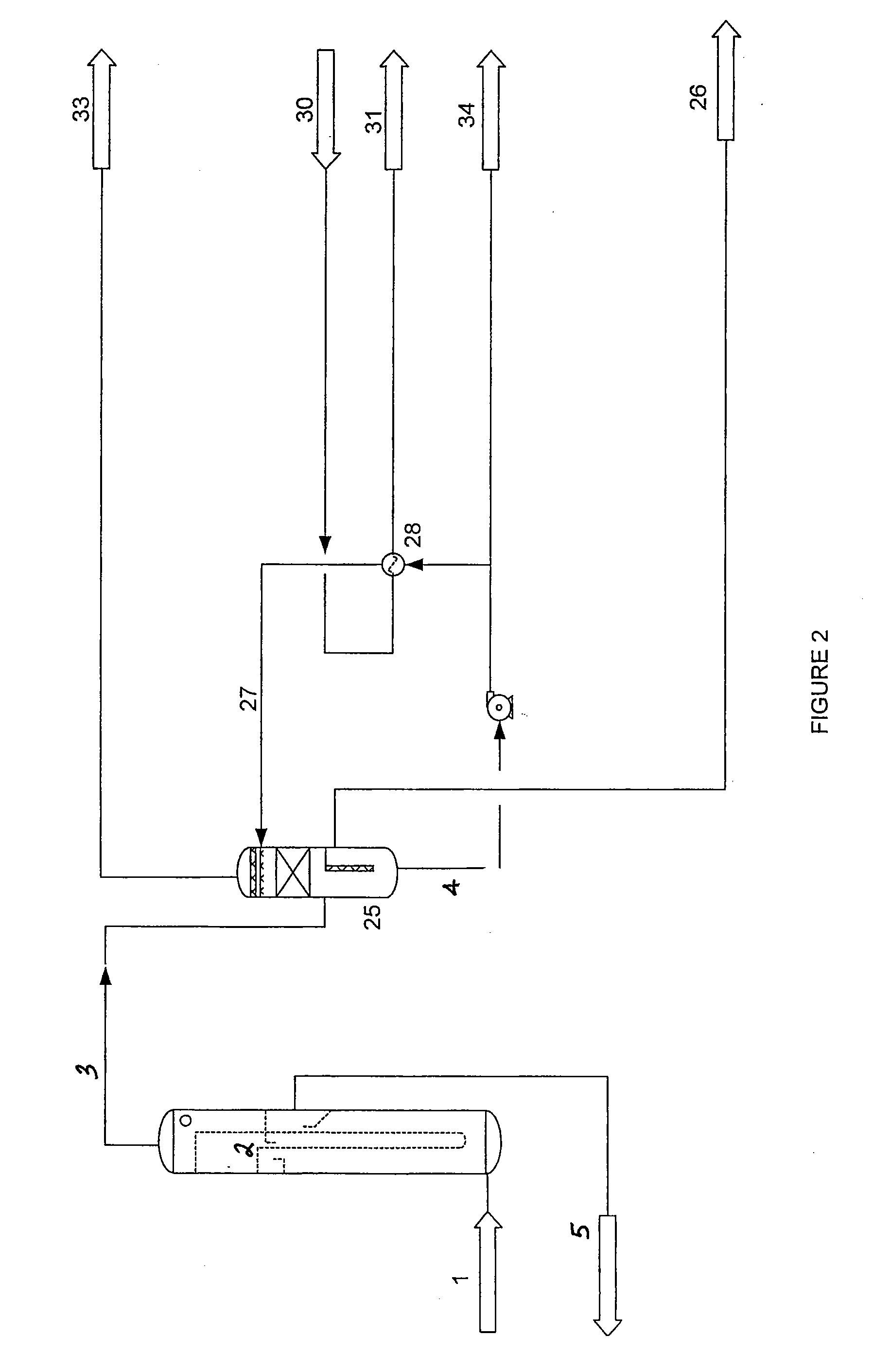
[0014]Three basic techniques may be employed for producing a synthesis gas, or syngas, which is used as the starting material of a Fischer-Tropsch (“FT”) reaction. These include oxidation, reforming and autothermal reforming. As an example, a Fischer-Tropsch conversion system for converting hydrocarbon gases to liquid or solid hydrocarbon products using autothermal reforming includes a synthesis gas unit, which includes a synthesis gas reactor in the form of an autothermal reforming reactor (“ATR”) containing one or more reforming catalysts, such as a nickel-containing catalyst. A stream of light hydrocarbons to be converted, which may include natural gas, is introduced into an ATR along with an oxygen-containing gas which may be compressed air, other compressed oxygen-containing gas, or pure oxygen. The ATR reaction may be adiabatic, with no heat being added or removed from the reactor oth...


PUM

PropertyMeasurementUnit
Temperatureaaaaaaaaaa
Fractionaaaaaaaaaa
Volumeaaaaaaaaaa

Abstract

The invention provides an improved hydrocarbon recovery process of the Fischer-Tropsch process overhead stream using a scrubber system. Described is a process for recovering Fischer-Tropsch hydrocarbons from a reactor exit gas produced from a Fischer-Tropsch synthesis operation. The process includes (a) passing the reactor exit gas to a gas/liquid contactor; and (b) withdrawing a lean tail gas stream, a light hydrocarbon stream, and a water stream from the scrubber.

Description

PRIOR RELATED APPLICATIONS[0001]This Application claims priority over U.S. Provisional Application No. 60 / 820,028, filed Jul. 21, 2006, which is incorporated herein in its entirety.FEDERALLY SPONSORED RESEARCH STATEMENT[0002]Not applicable.REFERENCE TO MICROFICHE APPENDIX[0003]Not applicable.FIELD OF THE INVENTION[0004]The invention relates to an improved process for recovering hydrocarbons from a Fischer-Tropsch overhead stream using a scrubber system.BACKGROUND OF THE INVENTION[0005]Fischer-Tropsch synthesis operations produce hydrocarbons having a wide range of molecular weights. In general, Fischer-Tropsch hydrocarbons are recovered from the Fischer-Tropsch reactor along with a tail gas. Tail gas represents an overhead product from the Fischer-Tropsch synthesis operation containing the light hydrocarbon fraction plus carbon oxides, hydrogen, and water vapor. Tail gas is generally considered a low value product which may be recycled to the reactor or burned locally as fuel. Altho...

Claims


Application Information

Patent Timeline
IPC IPC(8): C07C27/00
CPCC10G2/32
Inventor INGA, JUANRECORD, TSUNGANI
Owner REG SYNTHETIC FUELS LLC
Why Eureka
Try Eureka